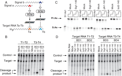
Figure 2.
Basic features and properties of biosensor device. (A) The molecular components used in (B), (C) and (D); BDa and BDb stand for either BD1 and BD2 (biosensors for Sig1 and Sig2, respectively), or BD3 and BD4 (biosensors for plk1 and bcl2 signals, respectively). Colored arches in signals represent trigger-sequence motifs in their 3′-UTR; colored arches in the target RNA represent target sequences (Ta or Tb) for the corresponding S:As siRNA outputs. Target RNAs used in the cleavage assay were cap-labeled by 32P-GTP (Supplementary Methods). (B) The activities of the biosensor devices ‘D’ and their predicted siRNA outputs ‘O’ as analyzed by RNA cleavage assay in the Drosophila embryo lysate. Target RNA T1–T2 was used for BD1 and BD2, and target RNA T3–T4 was used for BD3 and BD4; control, a 600-nt control RNA (CK600nt) was used to normalize the loading of samples in each lane; mock, nonspecific siRNA. (C) Biosensor devices in which the As strands were labeled with fluorescein at the 3′ terminus were incubated with excess molar amounts (4× or 8×) of 140-nt scrambled RNA (Mock) or 140-nt signal RNA at 25°C for 1 h. Samples were analyzed by native polyacrylamide gel. (D) Testing the specificity of the biosensor devices in the Drosophila embryo lysate. Different biosensors were incubated with their cognate and non-cognate signals. Sx:Asx, the mixture of S1:As1, S2:As2, S3:As3 and S4:As4; mock, non-specific siRNA.

