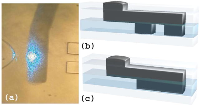
Fig. 4.
(a) Image of a beam blocking bar between a lens (left) and a waveguide (right). Apertures (b) and beam blocking bars (c) are made by filling channels in the light guiding layer (darkest region, second to bottom) via a filling channel in the capping layer (represented by the top two layers, the lower portion containing filling channels and the upper portion containing punch holes for channel access). The aperture (b) will block stray light, allowing light to pass only through the center portion. The beam blocking bar (c) is used to verify the light blocking capabilities of the filled channels.

