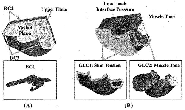
Fig. 3.
Boundary and loading conditions used in the FE model. (A) Boundary conditions (BC). BC1: The femur and the pelvis were assumed as rigid bodies and constrained to obviate rigid body motion; BC2: The upper plane and the medial plane were constrained against the anterior-posterior and medial-lateral motions; BC3: Ends of tissues that connect to the rest of the body (distal end to thighs, proximal end to lumbar region) were constrained against longitudinal motions. (B) General loading conditions (GLC) and the input load (Specific loading condition) for the model. GLC1: A “skin initial strain” was applied into the skin layer of the FE model; GLC2: A “muscle tone” which was 1% of maximal muscle force estimated from Fmax = σmax × PCS A, was applied along the line of action of each muscle. In the above equation, σmax is the maximal muscle tension [22]; Input load (specific loading condition): an interface pressure of 20.34 kPa was applied to the buttock sitting surface of the model, (a) Boundary conditions (b) Loading conditions.

