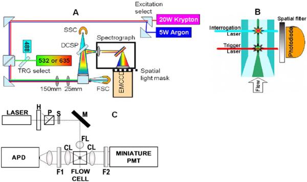
Figure 1.
(a) Top-view schematic of Raman full-spectral flow cytometer experimental apparatus with grating-spectrograph dispersive element. Flip mirrors are used to allow selection of krypton or argon laser excitation and 488 nm or diode laser (532 or 635 nm) for the trigger (TRG) laser. DCSP: dichroic short pass filter, SSC: side scatter PMT detector, FSC: forward scatter photodiode detector. (b) Sideview schematic of flow cell showing spatial separation of trigger and interrogation lasers. Sample stream (dark central region) is hydrodynamically focused by the surrounding sheath flow (lighter colored region). (c) Diagram of the high-sensitivity cytometer optics breadboard, flow cell, and sample holder. H, half wave plate; P, polarizer; S, shutter; M, mirror; FL, focusing lens; CL, collection lens; F1, filter 1; F2, filter 2; PMT photomultiplier tube and APD avalanche photodiode.

