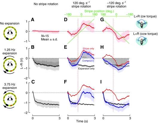
Fig. 3.
The turning response to a compound stimulus depends on the strength and relative configuration of the expansion and object components. The mean (±s.d.) turning response to a non-moving, static grating pattern is shown in A. (B,C) The mean turning response away from a laterally positioned (on the right) focus of expansion (FOE) for the two speeds tested. (D,G) The mean turning response to a dark stripe rotating in both directions over a stationary (low contrast) background is shown; stripe position plotted in green. These stimuli were combined such that the FOE is fixed at the sides while the object is rotated at a constant velocity. In the remaining panels (E,F,H,I) the response to the combined stimulus is shown in blue, while the response to the stripe alone is plotted in red (reproduced from panels D,G) and the response to the expansion-only stimulus is plotted in black (reproduced from panels B,C). The broken red lines show the locations of the zero crossing of the mean stripe response, which precede the time when the stripe actually crosses the midline. The icons depict the conditions with the stripe rotating in the clockwise direction, corresponding to the positive speed trials whose data are shown in the middle column. The vertical black lines in B, E and H mark the times at which the pattern was updated with a one frame advance, to emphasize the repetitive surges in the turning response away from the FOE (downward in this figure), that are a feature of the responses to the slower expansion stimulus. L>R, difference between left and right wingbeat amplitudes; cw torque, clockwise torque; ccw torque, counter-clockwise torque.

