SUMMARY
The remodeling that occurs after a posterolateral myocardial infarction can alter mitral valve function by creating conformational abnormalities in the mitral annulus and in the posteromedial papillary muscle, leading to mitral regurgitation (MR). It is generally assumed that this remodeling is caused by a volume load and is mediated by an increase in diastolic wall stress. Thus, mitral regurgitation can be both the cause and effect of an abnormal cardiac stress environment. Computational modeling of ischemic MR and its surgical correction is attractive because it enables an examination of whether a given intervention addresses the correction of regurgitation (fluid-flow) at the cost of abnormal tissue stress. This is significant because the negative effects of an increased wall stress due to the intervention will only be evident over time. However, a meaningful fluid-structure interaction model of the left heart is not trivial; it requires a careful characterization of the in-vivo cardiac geometry, tissue parameterization though inverse analysis, a robust coupled solver that handles collapsing Lagrangian interfaces, automatic grid-generation algorithms that are capable of accurately discretizing the cardiac geometry, innovations in image analysis, competent and efficient constitutive models and an understanding of the spatial organization of tissue microstructure. In this manuscript, we profile our work toward a comprehensive fluid-structure interaction model of the left heart by reviewing our early work, presenting our current work and laying out our future work in four broad categories: data collection, geometry, fluid-structure interaction and validation.
Keywords: biofluid-structure interactions, ischemic mitral regurgitation, imaging based finite element models
1. Introduction
Computational fluid-structure interaction (FSI) studies of the heart have a long - but sparse - history, beginning with the seminal introduction of immersed boundary methods in 1972 by Dr. Charles Peskin [1]. Nearly all later studies avoided consideration of the mitral and aortic valves, and were instead focused on the fluid-dynamics of either diastolic filling [2, 3, 4, 5] or systolic ejection [6]; the few studies that did consider valvular-interaction in addition to ventricular-interaction considered only the aortic valve [7]; and all but a very recent few have been based on highly idealized geometries and material properties [8, 9]. These idealizations have characterized in-vacuo numerical models of the myocardium to a somewhat lesser extent (e.g. [10, 11, 12, 13]). At the same time, a number of studies have considered the fluid-structure interaction of native tissue valves. Of these, the majority have focused on the aortic valve or the aortic position [7, 14, 15, 16, 17, 18, 19, 20, 21, 22, 23], while only two [24, 25] have considered the native mitral valve, and another a chorded mitral prosthesis [26]. The geometry of the majority of these valvular models was based on anatomical descriptions of Thubrikar et al. [27], with the notable exceptions of the work of Grande-Allen [28], which was based on magnetic resonance imaging data, Kunzelman [29] which was based on serial histology, and Votta [30] which was based on invivo ultrasound data.
The simplification of the cardiac geometry and tissue microstructure in cardiac FSI models has enabled interesting studies that have increased our understanding of cardiac fluid-dynamics. A careful characterization of both of these is critical to a predictive analysis of both cardiac mechanics and surgical intervention. Cardiac (as distinct from cardiovascular) computational modeling, in general, has been slow to benefit from the rapid developments in image processing that have permeated many other fields. In part, this has to do with the fact that only ex-vivo hearts can be imaged with sufficient resolution to capture the full cardiac geometry and fiber orientations; this is problematic since ex-vivo geometries and in-vivo geometries are quite different, especially following fixation. However, a bigger barrier to a predictive analysis has been the absence of the mechanical influence of the cardiac valves. The strong influence of the cardiac valves on the fluid dynamics of the heart is obvious. In addition, the valves have a strong influence on the solid mechanics of the heart. The anterior leaflet, for example, is continuous with the the aortic valve and the wall of the ascending aorta. However, the greatest mechanical coupling between the ventricle and the cardiac valves is due to the chordae tendinae of the mitral valve that connect the free-edges of the anterior and posterior mitral leaflets to the papillary muscles and thus to the left ventricular wall. These chordae also act as secondary orifices for blood flow, creating a dynamic interface between blood and tissue that is geometrically complex.
Ischemic mitral regurgitation (MR) is a clinical pathology that involves both the mitral valve and the left ventricle in terms of the dynamic interaction between blood and tissue. Following a postero-lateral myocardial infarction, the infarct loses contractile function and expands. Infarct expansion and compensation via the Starling relationship leads to an increase in left ventricular (LV) volume at end-diastole. Repositioning of the papillary muscle relative to the mitral annulus creates a traction on the chordae such that the mitral leaflets close below the valve plane and no longer coapt. Cardiac and intravalvular flows are pathologically altered, with blood regurgitating into the left atrium during systole. The clinical consequences of ischemic MR are dramatic over time, although the exact contributions of the mitral regurgitation per se and infarct expansion to ventricular remodeling remain unclear. Both acute and chronic regurgitation can lead to pulmonary edema [31], and relatively small changes (25 mL) in end-systolic LV volume are associated with exponential increases in mortality [32]. The goal of surgical intervention is to correct the mitral regurgitation and to reduce stresses in the remote myocardium and infarct borderzone so that ventricular remodeling is slowed or reversed. These goals may not be automatically complimentary, depending on the surgical intervention. While regurgitation is clinically observable, stress is not. Computational modeling of ischemic MR and its surgical correction is attractive because it enables an examination of whether a given intervention addresses the correction of regurgitation (fluid-flow) at the cost of abnormal tissue stress.
In this manuscript, we present our ongoing work toward a comprehensive fluid-structure interaction model of ischemic mitral regurgitation. First, we review our early work as a motivation for our current efforts. Next we present novel contributions in the area of image analysis, grid generation, computational geometry, inverse methods and numerical schemes for strongly coupled fluid-structure problems that move us toward our goal of a comprehensive fluid-structure interaction of the heart. Most, if not all of these contributions have implications for biological fluid-structure interaction problems in general. Next we outline areas of improvement that are needed and are planned in the near future for this effort. Biological fluid-structure interaction problems are challenging not only due to the demands of the coupling numerics, which is still the subject of much research, but also because the analyst must work in many disparate disciplines. To simplify our presentation, sections on early, present and future work are organized into four broad categories: data collection, geometry, fluid-structure interaction and validation.
2. Finite Element Analysis of The Mitral Valve: Early Work
Our early analyses of the fluid-structure interaction of the mitral valve have been previously published [33, 34, 25, 35]. Here we briefly summarize that work to serve as background for our presentation of our current work.
2.1. Data Collection
Material properties and material anisotropy for the fluid-structure model of the mitral valve were obtained from bench top tests. Collagen fiber orientation was determined from a small-angle-light-scattering (SALS) mapping [36]. A drawback of SALS is that it requires that the valve leaflets be excised and rendered two-dimensional. Nevertheless, by dividing the tissue into quadrants, we were able to create a case-specific mapping between the data and the computational model. Having defined the local material anisotropy, we parameterize a constitutive model for mitral tissue elasticity with bench top biaxial mitral tissue tests [37, 38]. Such material tests also require tissue excision. Briefly,
| (1) |
where S is the second Piola-Kirchhoff stress, C is the Lagrangian metric, p is a Lagrange multiplier to force the constraint of incompressibility, Sf (θ, C) is a fiber stress-strain rule, R(θ) is a probability distribution function, and a0 ⊗ a0 (θ) governs the orientation of a fiber family in the 2D plane. We assumed that Sf (θ, C) was given by
| (2) |
As formulated, Equation 1 must be numerically integrated.
2.2. Geometry
The mid-diastolic surface geometry (1) of the mitral valve leaflets and papillary muscle tips, as well as the number and radiation pattern of the chordae tendinae were developed from fresh porcine hearts [29]. Briefly, three porcine mitral valves were fixed in resin in both their loaded and unloaded configurations, cut into cross-sections, digitized and averaged [29, 39]. The unloaded geometries were triangulated to represent the leaflet geometry in the finite element model. Loaded geometries were available for comparison with model predictions. At discrete locations on the anterior and posterior leaflets thickness was recorded [29, 39]. Thickness for the entire leaflets was interpolated from these data. Chordal insertion and diameters were recorded as well. Importantly, the leaflets, papillary muscles and chordae were approximated as being symmetrical about the leaflet’s mid line - i.e. the mid line perpendicular to a line connecting the commisures [29, 39].
This geometry has yielded many important insights into the mechanics of the mitral valve. However, for application to modeling ischemic mitral regurgitation there are several ways it can be improved upon. First, dynamic video fluoroscopic data suggest that while the mitral annulus is approximately symmetric about the septal-lateral mid-line [40, 41, 42], significant asymmetry exists with regard to subvalvular geometry and motion, both in normal function and in pathology [40, 41, 42, 43]. Since ischemic mitral regurgitation flows from myocardial dyskinesis that affects the posterolateral papillary muscle, that symmetry is further broken. Although, further evolutions of the model did include the entire valve allowing for the analysis of asymmetric perturbations [44, 45, 46], these were not included in the FSI analysis. Most importantly, the chordae and leaflets were topologically one- and two-dimensional, respectively. For accurate fluid-structure interaction of the whole mitral geometries, especially in the neighborhood of the interface, chordae tendinae and leaflets must be both geometrically and topologically three-dimensional. These goals are now achievable with advanced image analysis, as will be later described.
2.3. FSI
Our early approach to FSI has been presented elsewhere [33, 47, 48, 49]. Here we reiterate the key points and results as they apply to our early FSI analysis of the mitral valve in order to give context to the newer approaches presented herein. A laminar Eulerian formulation was used to model the blood domain, which was assumed to be a compressible, Newtonian fluid. Specifically, the deviatoric stress depended linearly on the shear rate, while compressibility was governed by the equation of state
| (3) |
where p is the pressure, K the blood bulk modulus and J the Jacobian or volume ratio. For computational efficiency, the bulk modulus was lowered to 2:5 × 10⁴ kPa from an estimated value of 1:0 × 107 kPa. All other fluid variables were assigned their physical, if linear, properties. Fluid and solid domains were topologically distinct; equations of motion for each were solved by explicitly integrating in a staggered fashion. Momentum was advected with a second-order Van-Leer method. To effect the exchange of momentum between fluid and solid, the nodes of the Lagrangian membrane elements were made to interact as boundary nodes with the fluid. The Lagrangian solid mesh was advanced one time-step. Thereafter, the boundary nodes were applied as boundary conditions to the Eulerian fluid elements, which reacted by altering their velocity and pressure. These were then treated as boundary constraints on the Lagrangian structure at the next time-step.
More specifically, at each time step all of the fluid elements containing a structural node were identified. The structural nodal mass was then distributed to the fluid element nodes according to
| (4) |
where i is the nodal index and h is a weighting coefficient between 0.0 and 1.0. Similarly, the structural nodal force was distributed to the fluid according to
| (5) |
The new fluid nodal acceleration was
| (6) |
The structural nodal acceleration was constrained or matched to the fluid elemental acceleration as
| (7) |
Note the above summation implies that the formulation is limited to hexahedra. In addition, the structural nodal momentum was distributed to the fluid element nodes according to
| (8) |
with a new nodal velocity of
| (9) |
Finally, the structural nodal velocity was constrained to the fluid velocity, as
| (10) |
2.4. Validation
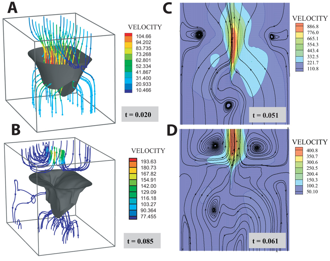
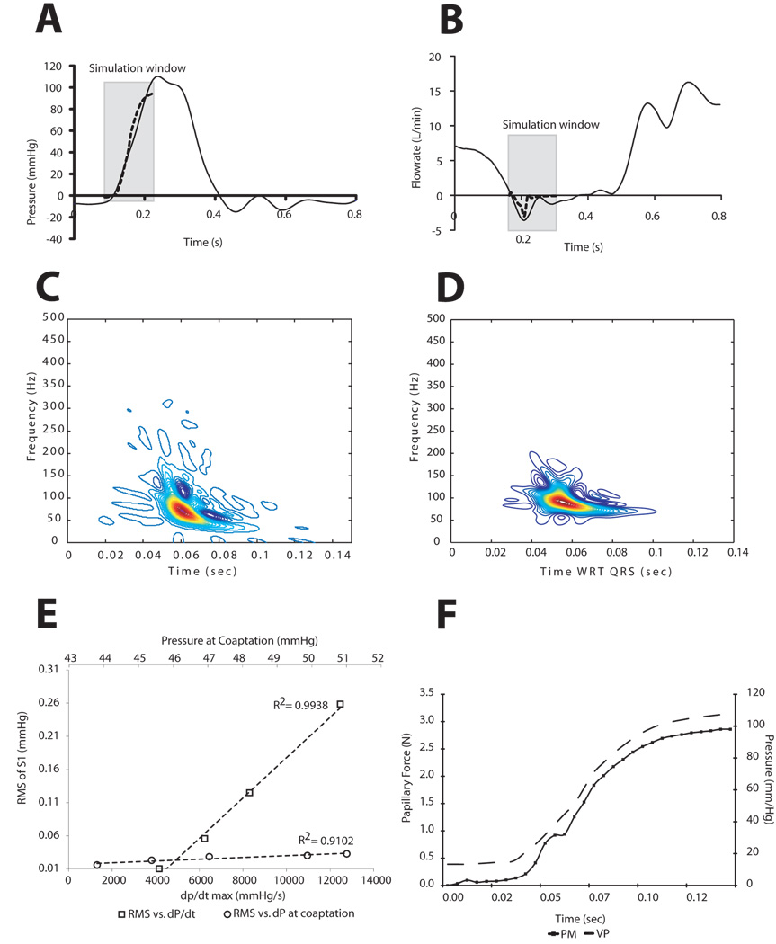
Streamlines at four time points in the cardiac cycle before and after coaptation are shown in Figure 2. Notable are the vortices that develop upon coaptation. The predicted transmitral pressure and flow showed excellent agreement with published in vitro trans-mitral pressure and flow data from the Georgia Tech left heart simulator [50]. Specifically, the peak closing flow of 3.1 L/min compared well with a measured peak closing flow of 3.6 L/min (Figure 3B). The well-known non-stationarity of the acoustic vibrations radiating from the mitral valve was observed in both the computational model and measured thoracic S1 from sheep in our laboratory. The predicted time-frequency signature was found to have a downward glide in frequency with a maximum at 72.0 Hz occurring at 0.0604 seconds from pressure crossover. Similarly, the average maximum peak frequency for the measured thoracic sounds was 71:7 ± 2:8 Hz and occurred 0:071 ± 0:003 seconds from the peak of the QRS wave in the EKG. To further test model acoustic predictions, we varied both the absolute pressure gradient across the valve at coaptation as well as the pressure derivative (dP/dt). The linear relationship between the ventricular pressure derivative and the root-mean-squared amplitude of the acoustic pressure has been amply documented [51, 52, 53, 54, 55]. Our model was able to predict the linearity of these relationships - remarkable given the strong nonlinearity of the system. The relationship between papillary muscle force and the left ventricular pressure curve (Figure 3F) is also well-documented [50, 56, 57]. The predicted value of 2.6 N for the summed papillary muscle agrees quite well with both in-vivo and in-vitro papillary muscle force measurements.
Figure 2.
Streamlines at four time points during the simulation: A) the beginning of the simulation before diastolic flow has reversed; B) the end of the simulation after coaptation and as the atrial flow begins to settle; C & D the moments preceding and immediately following coaptation, respectively. Note: chordae have been omitted from the figure for clarity. Panels C & D are cross-sections at the symmetrical midline shown in Figure 1.
Figure 3.
Predictions of the computational model compared to experimental in-vitro (A & B) and animal (D, E & F) data: (A) transvalvular pressure, (B) trans-mitral flow. Solid line - reference. Dotted line - computational model. The predicted closing flow shows excellent agreement with in vitro data over the simulation window [50]. Simulated intraventricular S1 (C) and measured thoracic S1 (D). Linear relationship between dP/dt max and S1 RMS (open squares). Linear relationship between dP and S1 RMS (open circles) (E). The increased dP/dt has a more profound effect on acoustic power. (F) Predicted anterolateral papillary muscle force (solid line with squares) and ventricular pressure (broken line).
In short, model predictions showed excellent agreement with a variety of available data, and therefore was appropriate for the modeling questions we posed at the time: 1) what are the hemodynamics of the mitral closing sound; 2) what influence do collagen orientation, organization, density and stiffness have on mitral valve dynamics; 3) what is their relationship to disease of the mitral tissue; 4) how are all of these influenced by or manifestations of flow. We found that the flow was abruptly decelerated upon closure, resulting in large scale eddies behind the valve accompanied by lesser eddies on the ventricular side. Superimposed on the large scale motion of the fluid, pressure oscillations exchanged momentum between tissue and fluid. These oscillations were in the audible range but were quickly damped by the fluid viscosity. The effect of the coupled system was to lower the frequency of these pressure waves over time, resulting in the commonly observed non-stationary glide of the first heart sound. Furthermore, we found that the energy in these vibrations was sufficient to account for the total acoustic power measured on the thorax, and that the peak frequency was a nonlinear function of both the transvalvular pressure as well as the pressure derivative - a complicating factor for those who would correlate frequency with disease. With regard to the influence of the microstructural constituents of the mitral valve tissue, we found that perturbations that preserved valvular anisotropy - for example increased fiber stiffness or volume fraction - also preserved valve function, albeit with increased stress. In contrast those that did preserve valve anisotropy - for example a modest increase in the isotropic component or an increase in the fiber splay - led to both substantial regurgitation and increased stress. This functional relationship between anisotropy and regurgitation.
As a final note, we point out that non-stationary acoustics is an attractive component to validation of FSI models of cardiac valves. This is because in strongly coupled systems the modes of vibration will have components that belong to the fluid, and to the solid as well as to the coupled system [58]. In turn, the frequency components of the tissue will be proportional to stress. Thus, while stress cannot be directly measured, it can be indirectly measured.
3. Strategies for Modeling Ischemic Mitral Regurgitation: Present Work
Modeling ischemic mitral regurgitation and its surgical correction requires an accurate, imaging-based representation of in-vivo geometries and automatic quality construction of an interface-compatible computational grid. Due to the topological and geometrical complexity of the problem, reconstruction and discretization must be fully automatic, scale-invariant and reflective of the physical and computational demands of fluid and solid domains separately but compatibly. In this section we present novel schemes for distilling geometry, grid generation, voxel-to-grid mapping from imaging data to an arbitrary unstructured grid, warping of ex-vivo geometries to in-vivo landmarks, inverse analysis, Lagrangian fluid-structure interaction numerics and validation.
3.1. Data Collection
Data for detailed left-heart geometry and myofiber architecture come from standard proton magnetic resonance imaging with a Fluorocarbon contrast agent and from magnetic resonance diffusion tensor imaging, respectively. Here we focus on image processing and computational geometry.
3.1.1. Image Segmentation
A full description of our segmentation is beyond the scope of the present manuscript. Here we outline the main points. To assure proper segmentation of the heart tissue and enclosed blood, a multimaterial voxel assignment segregates voxels into four material types: blood (Mb), heart tissue (Mh), other (Mo), and disputed (Md).
| (11) |
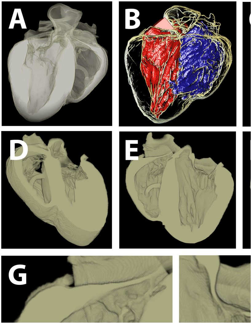
where Md is a fuzzy set that is the intersection of blood and tissue, and tn are intensity thresholds. Encapsulated disputed material is reassigned to the surrounding material when the enclosing material is all of the same material type (blood or tissue). This is accomplished by a depth-first recursive search algorithm that follows the 26-adjacency connectivity of disputed material points and tracks the range of material types bounding the 3D pocket of disputed material. In cases where the disputed material is bound by more than one other material type, those voxels remain disputed, but are flagged for guided manual resolution in a custom 3D image material editor, allowing rapid reassignment of material as appropriate. A secondary function of this editor is to highlight adjoining voxels of the same material with ambiguous connectivities, such as two voxels of the same material connected only at a corner. These connectivities require modification in order for the Marching Cubes algorithm [59] to produce valid surfaces. Figure 4 shows an ex-vivo segmentation of a sheep heart, with a physical resolution of ~ 250µm.
Figure 4.
Semi-automatic multi-material segmentation of ex-vivo sheep heart. A) volumetric visualization of whole heart. B) left and right ventricular blood masses in whole heart transparency. C) whole heart transparency. D & E) cut-away sections though the long-axis of the heart, showing both atrioventricular valves (tricuspid and mitral on the left and right hand sides respectively). F) blood with long-axis cut-away. G & H) details of tricuspid and mitral valves.
3.1.2. Diffusion Tensor Imaging and Mapping
As with the mitral valve alone, it is necessary to associate fiber angles with our computational grid. However, unlike the 2D SALS data for the mitral valve, myofiber orientations have a complex three-dimensional architecture and must be determined using magnetic resonance diffusion tensor imaging (DTMRI). Our collection of this data has been previously described [60]. Here we focus on the mapping, and formulate the problem in such a way that the data could come from volumetric imaging data or indeed volumetric histology data.
To associate the diffusion tensor data with our computation grid, we developed a fast algorithm for mapping cell fields between unstructured meshes that cohabit the same three-dimensional geometric domain, within a tolerance [61]. The tolerance is necessary because geometry in an image is implicit, while the geometry of a computational grid is explicit. Furthermore, operations of smoothing and surface adaptivity imply some deformation of the geometry. The imaging data is of course a Cartesian grid. However, we formulate the problem as an unstructured-to-unstructured mapping in order to address the general class of problem. The approach consists of computing a sparse matrix of intersection volumes Vij between the j’th element of the ’source’ mesh and the i’th element of the ’destination’ mesh in 𝒪(N log N) time, where N is the number of nonzero Vij. To efficiently find corresponding local neighborhoods of intersecting cells we perform a coordinated walk on source and target grids, which is an 𝒪(N) process. Subsequently, all Vij are reordered such that they can be packed into a sparse matrix. This need only be done once, and then a sparse matrix-vector multiply can be rapidly performed once for each direction cosine (Figure 5). It is important to note that the algorithm requires no a priori mapping between the image and the grid. With a geometry as complex as that represented by Figure 4, such an a priori mapping would be clearly impossible. As a final note, we point out that the mapping is geometric and that therefore any cell field can be mapped. We have previously speculated that the secondary and tertiary diffusion tensor diffusivities may encode other tissue parameters such as extracellular volume fraction [62]. This raises the possibility of directly characterizing constitutive parameters as part of an inverse analysis.
Figure 5.
Automatic mapping of 3D cellular information. Data is the direction vector of the myofibers in a sheep heart, as revealed by diffusion tensor MRI. A) the direction and magnitude of the vector in a voxelated MRI dataset. B) The overlap between the unstructured grid (grey) and the voxel grid (green). Note that the algorithm is very tolerant of small geometric mismatching. C) The vector field mapped onto the unstructured grid.
3.1.3. Inverse Analysis
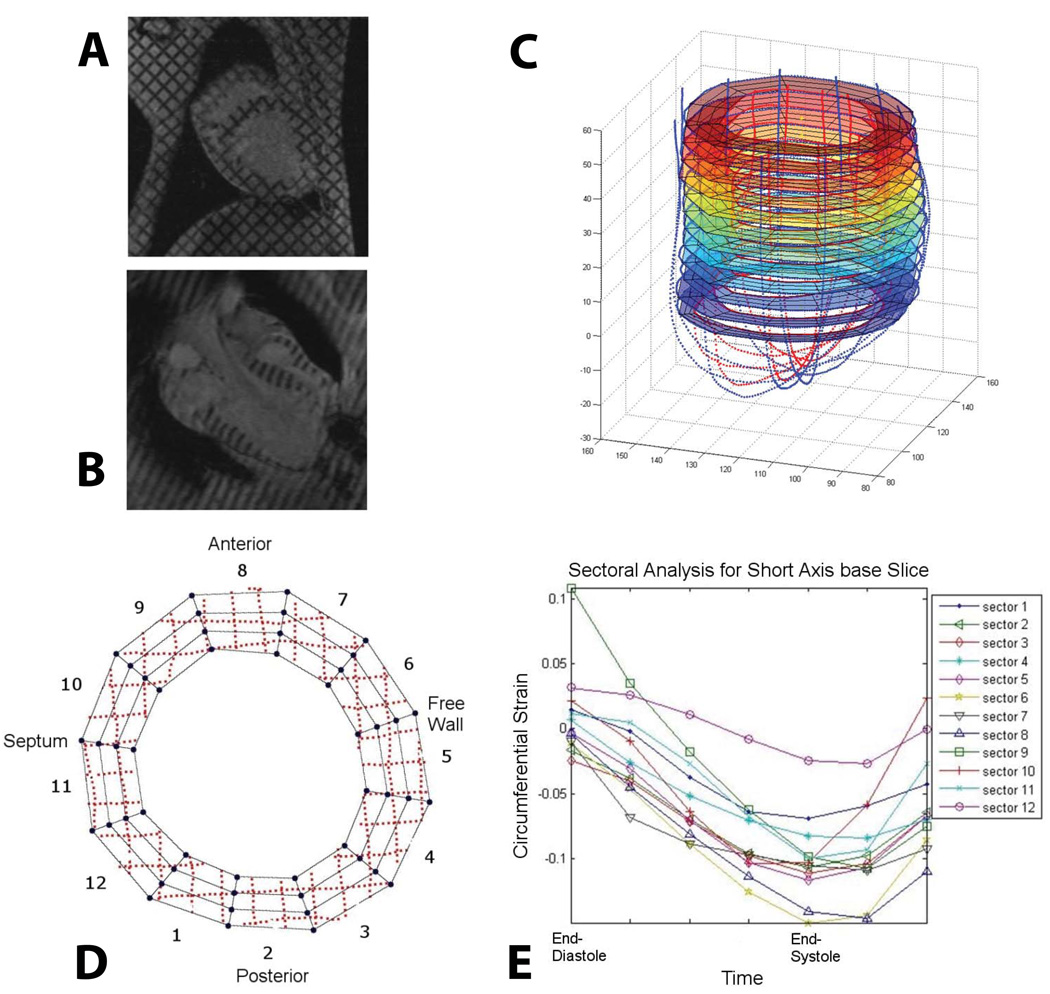
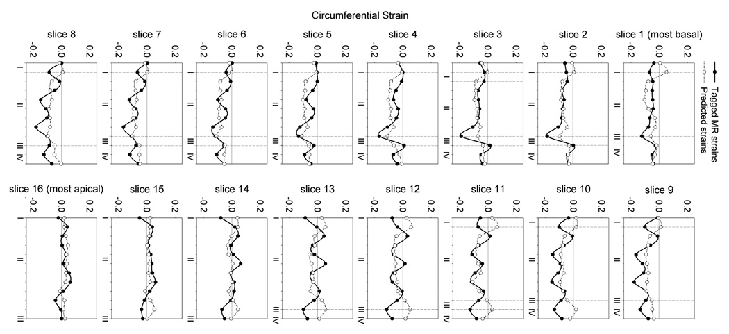
From a microstructual point of view, myofiber orientation is but one component of a mechanical framework that is not only both anisotropic and highly nonlinear, but also, and more importantly, heterogeneous and still somewhat unknown [63]. From a mechanical point of view, of course, it is convenient to make an assumption of a continuum, but challenges remain. For example it is well-known that continuum properties differ greatly in-situ and ex-situ due to residual or "pre-stresses", water content, degree of cross-linking (as a result of fixation), temperature and so on. Furthermore, the heterogeneity remains. If tissue is a continuum, it is what we have termed a "slowly-varying continuum". These factors recommend nonlinear inverse methods as an important part of model parameterization. In general, these methods consist of a series of forward simulations that generate a dataset to be compared to the experimental data. Because inverse methods are designed for problems with complex boundary conditions they may be particularly well suited for enhancing information from medical imaging modalities such as MRI. Our efforts to date have been based on the Successive Response Surface Method (SRSM), and have been applied to valvular tissues [64], inflation testing of aorta [65] and most recently to the parameterization of myocardial material properties from tagged MRI data. Strain analysis and model versus computational predictions from this latter study are shown in Figure 6 & Figure 7.
Figure 6.
3D cardiac strain analysis from in-vivo tagged MR images. Endocardial and epicardial contours as well as segmented tag-lines were traced from (A) short and (B) long-axis MR images to create (C) a 3D geometry. (D) Each short axis slice was divided into 12 sectors and a 4D B-spline-based motion tracking technique was applied to the tag-line (dotted lines) deformations in order to calculate the Lagrangian Green’s strains in cylindrical coordinates. For each sector of each short axis slice, longitudinal, radial, (E) circumferential and shear strains throughout systole were determined.
Figure 7.
Circumferential strains predicted from the present FE model are generally in reasonable agreement with the values measured in-vivo from tagged MR images. Slice 1 is the most basal while slice 16 is the most apical. I is the posterior right ventricular insertion, II is the free wall, III is the anterior right ventricular insertion and IV is the septum. The area of largest discrepancy between the measured and predicted circumferential strains is at the insertion points of the right ventricle to the left ventricle since the right ventricle was not included in the model. Overall the minimized mean square error was 4.7, motivating the development of improved methods.
Details of the method may be found in the above and related citations, particularly [66] & [67]. Here we simply state that the SRSM differs from serial and gradient approaches to minimization by constructing a smooth approximation - a response surface -to model responses in multi-dimensional space. Parameter combinations are chosen by design of experiments criteria, in our case D-optimality [68, 66]. The global nature of the approach derives from its sequential application. The minimum of one set of simulations, or of one response surface, becomes the starting point for the next set of simulations. This cycle of forward solutions at selected points followed by the minimization of the objective function with respect to the response surface is repeated until the prescribed tolerance in the residual is reached. With each successive iteration, the parameter space is condensed and possibly moved with each set of experiments, such that the sampling is conducted on a smaller and smaller region [67]. This assures that, in the neighborhood of the global minimum, the response surface captures finer and finer features of the system response. Conversely, the approximate nature of the response surface over a wider parameter space at the start of optimization assures that the method is relatively insensitive to local rather than global minima, and similarly relatively insensitive to experimental noise [67].
For determining the active systolic myocardial parameters (see [69] for detials of the constitutive model), the mean squared error (MSE) was minimized. The MSE was defined as the difference between the computed finite element and experimental results (end-diastolic and end-systolic volumes and strains).
| (12) |
where n is the in-vivo strain point, N is the total number of in-vivo strain points, Eij,n is the computed strains at each strain point, VED and VSD are the computed end-diastolic and end-systolic LV volumes, respectively. The overbar represents experimental in-vivo measurements. Strain in the radial direction, E33, is excluded as it cannot be measured with sufficient accuracy with tagged MR images. So defined the MSE was minimized to 4.7, the results of which can be seen in Figure 7. While the fit is reasonable, two improvements are likely warranted, both of which imply a potentially large increase in the parameter space. First, passive constitutive parameters were not adjusted but assigned from previous studies. Second, we identified three distinct material zones rather than a more full discretization implied by the concept of a slowly-varying continuum. The trade off of an increased parameter space is increased computational expense, as well as increased covariance. This motivates the search and development of new methods.
3.2. Geometry
Below we outline our approach to constructing computable, quality grids from imaging data that are designed to support Lagrangian bio-FSI problems by automatically creating compatible interfaces between fluid and solid. We remand our discussion of registering these grids to in-vivo data in the section on future work.
3.2.1. Grid Generation
Imaging-based geometries, such as that represented by the sheep heart shown in Figure 4, represent clear challenges for generating quality computational grids for Lagrangian FSI in that the grid must be organized both by geometric scale and intrinsic properties, while resolving fluid-structure interfaces compatibly. Here we have to emphasize compatibility since we are adopting a Lagrangian approach to FSI. Generally speaking, we need only achieve geometric compatibility at the interface as solution variables can be interpolated at the interface. However, we impose the more rigorous constraint that nodal connectivity must be exactly matched at the interface. With regard to intrinsic properties, the wall of the heart is a laminated muscle consisting of three separate layers, each with a separate family of fiber and myocyte orientations. Thus, a grid of the heart muscle must be similarly layered. That same layering persists at the smaller scale of the heart, where, for example the musculature transitions into the connective tissue of the cardiac valves; or at an even smaller scale where the heart muscle involutes to become a network of coronary arteries. These transitions of scale are of course mirrored in the blood. The lumen of a coronary artery, for example, may be several orders of magnitude smaller than the span across a ventricle, and thus there is a need to equilibrate error over a range of meaningful scales.
Our approach to this challenge is based on the gradient-limited feature size (GLFS) [70], and is articulated in two complimentary scale-invariant gridding algorithms for quality layered tetrahedra for heart tissue [70] and quality prismatic-tetrahedral hybrid grids for the fluid [71]. The defined GLFS serves three functions: 1) a field for tangential adaptation of the surface grid, 2) a metric for creating layered tetrahedra, and 3) a speed function for construction of a prismatic boundary layer by application of the Generalized Huygens’ Principle [72]. Below we define the gradient-limited feature size and outline these algorithms with examples.
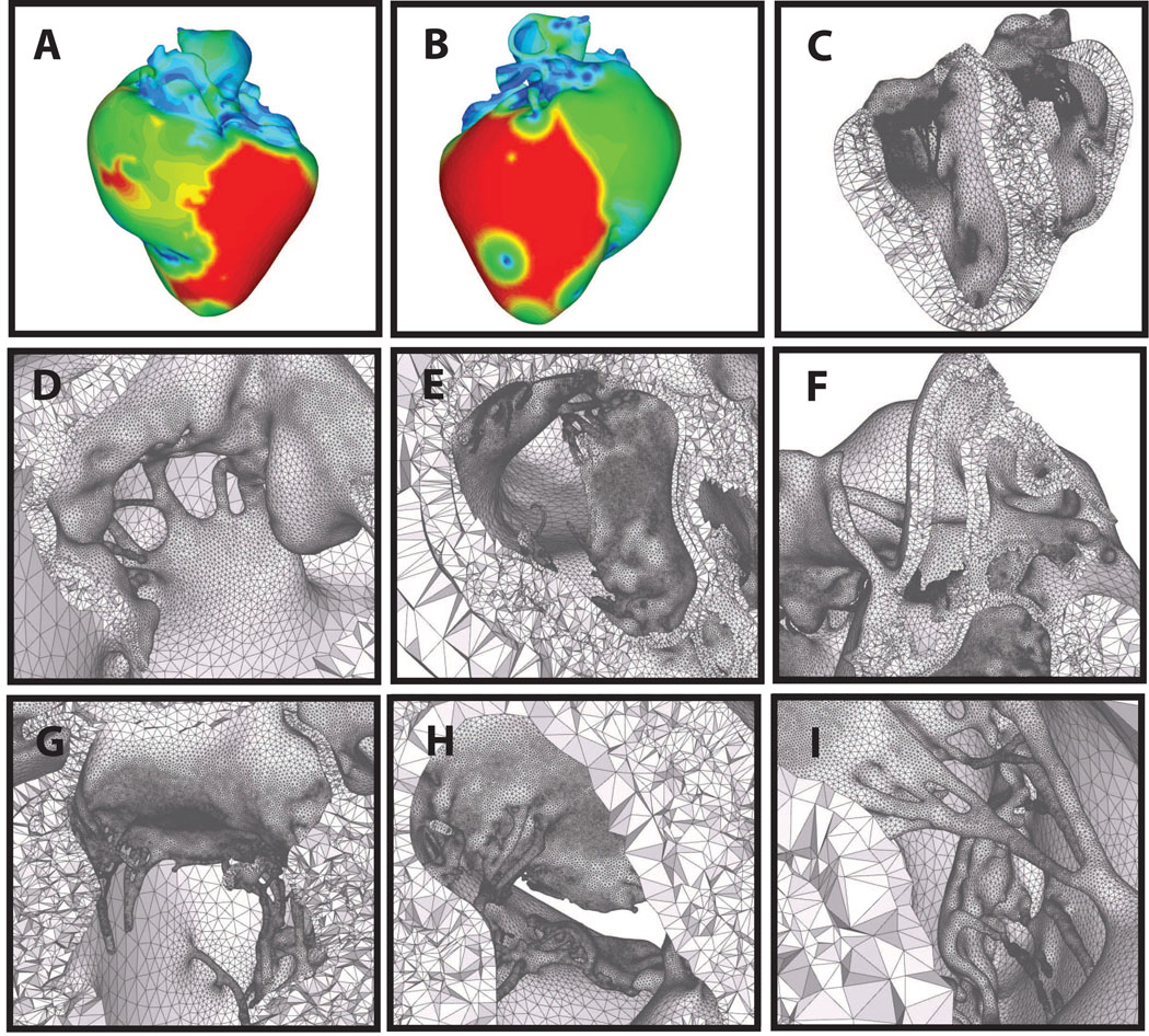
Let S be an oriented closed triangulated surface, which is derived from the isosurface of imaging data by the Marching Cubes algorithm [73, 74]. We allow S to consist of one large enclosing closed surface S0 and possibly any number of closed surface holes S1;…Sn inside S0. Any of the surfaces S0; S1;…Sn may have handles (i.e., have nonzero genus). As illustrated in Figure 8, we modify S to produce a high-quality surface mesh S′ by performing the operations of smoothing, refinement and de-refinement while limiting perturbations to a small fraction of a voxel. For any point x ∈ S, we define the “raw feature size” or “local diameter” F[x] as the length of the line segment formed by first shooting a ray from x in the direction of n̂[x], the inward normal at x, and then truncating the ray at its first intersection with S. That is
| (13) |
Since S is closed, with a robust normal n̂ (i.e. accurate and stable [75]) the ray proceeding from x in the direction n̂ will intersect S at least once, and hence F[x] is well-defined. Similarly, we also perform an “outwards” interrogation of the geometry to compute another raw feature size field Fout[x] using n̂out = −n̂in. This outwards value is finite in some areas (e.g., at concave parts of S). Fout[x] and is applied only to the adaptation of surface meshes, where it is necessary to respect a minimum sampling frequency [76].
Figure 8.
Automatic layered tetrahedral grid generation of the imaging data shown in Figure 4. Panels A & B: feature size field from two points of view. Panels D–I: details of the layered tetrahedral mesh. Shown are the mitral and tricuspid valves, with chordae. Note the size variation of the tetrahedra with respect to the local feature size.
The raw feature size computed by ray tracing is bounded (Fout may be unbounded), but it is sensitive to abrupt changes in the geometry. To address this, we first impose user-specified lower and upper bound to the feature size, denoted by Lmin and Lmax respectively. Thereafter, we compute a new feature size f[x] by modifying F[x], so that the spatial gradient is relatively insensitive to these changes in S. We accomplish this by performing a gradient-limiting procedure [70]. First, we initialize f[x] to F[x]. Given a bound G on the surface gradient of f[x], the algorithm places the directed edges that violate the gradient limit into a max-priority queue, ranked by the key
| (14) |
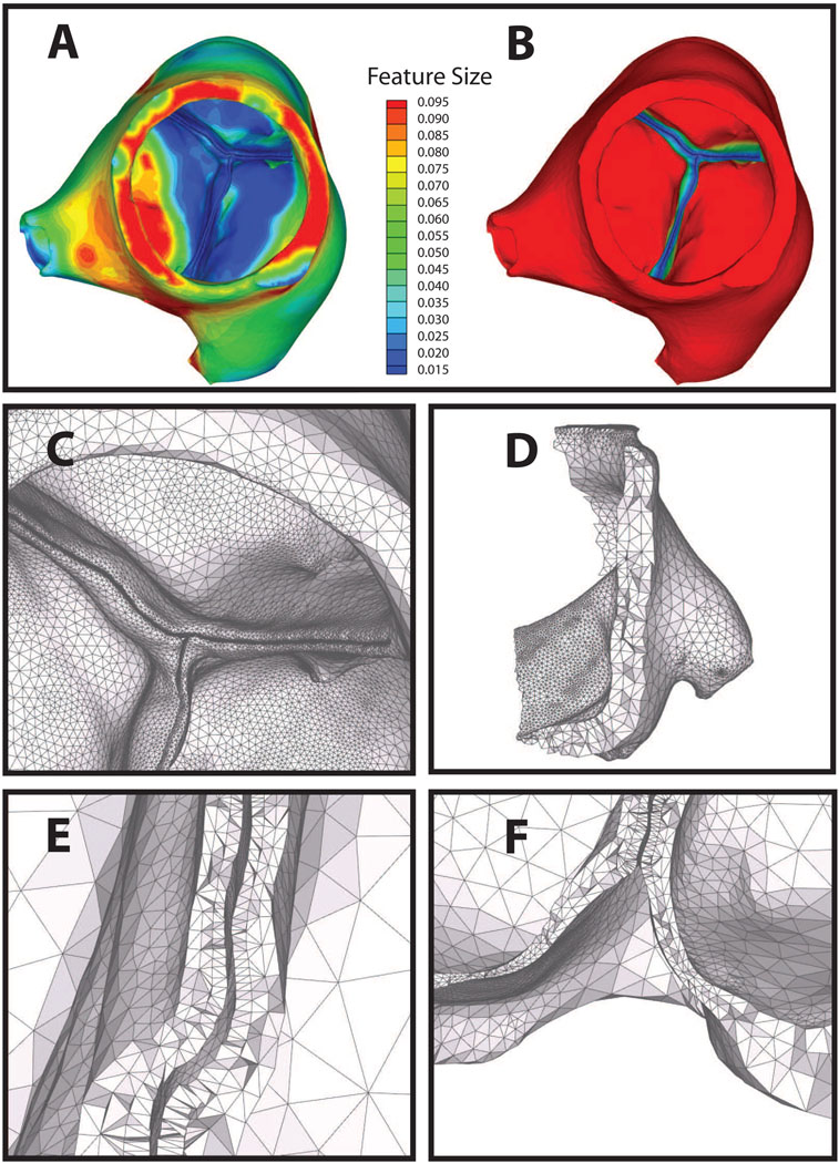
which measures how much the gradient violates the gradient limit for a directed edge on S. Let be the directed edge with the largest measure in the queue. We relax f[xi] to satisfy the gradient limit, recompute the measures for the incident edges of xi, and update the priority queue accordingly. The process continues until the queue is empty. For computational efficiency, ray-triangle intersections are queried within an axis-aligned bounding box (AABB) tree [77, 78] that contains at its leaf nodes the bounding box for each triangle. This algorithm has a complexity of 𝒪(N log N), where N is the number of triangles in S. Figure 9 shows both f[x] and fout[x] for an aortic valve from micro-CT. Note that the leaflets are separated by a single voxel, but that the integrity of the layers is preserved.
Figure 9.
Automatic layered tetrahedral grid generation of micro-CT data of a porcine aortic valve. Panel A: feature size field f[x]. Panel B: fout[x] field. Note the automatic detection of leaflets in close apposition. Panel C shows the surface adaptation by both f[x] and fout[x]. Panels D–F: details of the layered tetrahedral mesh. Note the preserved layering throughout. Also notable is the thick muscular shelf below the aortic cusps that are generally omitted in idealizations of the aortic geometry.
As described in [70], once a suitable tissue surface mesh has been obtained with edge lengths on the surface equal to about ctf[xi], where ct is a user definable parameter, we construct a layered tetrahedral volume grid (Figure 9, Figure 8 & Figure 10 by casting mi points in the direction n̂ (xi)
| (15) |
where here we have defined to be the surface points in S′. These points are connected with a modified Delaunay algorithm, where we disallow the insertion of if . In other words, if if is an interior point greater than a distance but less than a distance from xi, it is not inserted. Finally, the tetrahedral grid is improved with layer-aware, edge-flipping operations and a ’crushing algorithm’ that inserts nodes on the opposed diagonals of slivers and then merges the nodes together, eliminating the slivers. We note that the surface density ctf[xi] is independent of the normal direction layering, a concept that we use again for generating the fluid grid. The total process required 20 minutes and 90 minutes for aortic and sheep heart grids, respectively; once the user parameters are set, the process is fully automatic. Quality statistics for the sheep heart and porcine aortic valves are given in Table I.
Figure 10.
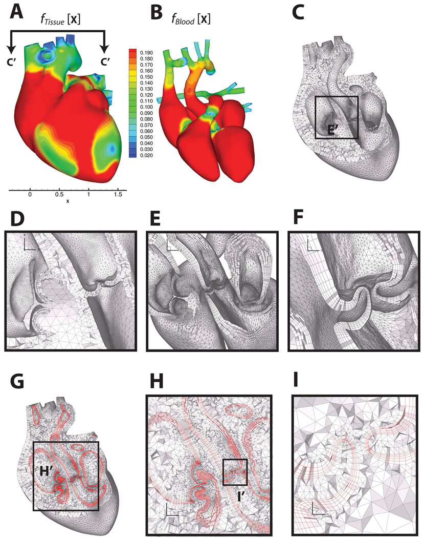
Multi-material boundary layer mesh of a human heart, consisting of heart tissue, blood boundary layer and blood domains. Panels A and B show the feature size field on the outer surface of the heart tissue domain and the blood domain, respectively. Panel B shows the feature size field on the outer surface of the blood domain. Panel C shows a cut through the heart muscle tessellated with layered tetrahedra [70], where the orientation of the cut plane is indicated in Panel A. Panel D shows the detail of the layered tetrahedral mesh of the heart tissue. Panels E and F are zoomed-in views on the regions of the cardiac valves, showing the prismatic boundary layer alone. Panels G, H and I show the prismatic boundary layer at about 25% of GLFS of the blood domain, sandwiched between the layered tetrahedra of the tissue and the Delaunay tetrahedra of the blood. Heart model and un-refined surface mesh are courtesy of the NYU Medical Center and Zhang et al. [85, 86].
Table I.
Tetrahedral mesh quality statistics (2 times the inscribed radius divided by longest edge) for the sheep heart (Figure 8) and aortic valve (Figure 9).
| < 0.01 | 0.01 – 0.02 | 0.02 – 0.05 | 0.05 – 0.1 | 0.1 – 0.2 | 0.2 – 0.5 | 0.5 – 1.0 | |
|---|---|---|---|---|---|---|---|
| sheep heart | 0 | 0 | 0 | 58 | 63813 | 2117885 | 4808113 |
| aortic valve | 0 | 0 | 0 | 19 | 8586 | 282815 | 369078 |
Having generated a quality layered tetrahedral grid for the heart tissue, we wish to create several layers of prisms at the Lagrangian interface between tissue and blood. There are several reasons for this. First, prismatic boundary layers are desirable for viscous flows, which tend to have strong gradients at the boundary due to wall shear stress, an effect that - as we have already mentioned - has been shown to be extremely important in cardiac/cardiovascular biomechanics. In addition, prismatic layers have been shown to be effective in reducing errors in turbulence, particle deposition, and mass-transfer problems [79, 80, 81, 82]. There is another reason, which we mention here but elaborate on in a future work. In biological fluid-structure interaction problems with a Lagrangian interface, prismatic boundary layers are also desirable near the interfaces, such as closing cardiac valves. In these cases, the direction of impaction is locally normal to the boundary, so it is aligned with axis of the prisms. Thus, prisms as opposed to tetrahedra are less prone to entanglement.
Our method advances a surface layer by solving the Lagrangian evolution equation,
| (16) |
where t denotes time, n̂ denotes unit surface normal, and f(x; t) denotes the GLFS, as defined above. Generating a layer of prisms reduces to marching the vertices in time by discretizing Equation 16. To avoid “swallowtails” [83] in strongly concave regions and in regions with large curvatures, we apply the face offsetting method in [72], which is based on a geometric construction called the generalized Huygens’ principle and numerical techniques of least-squares approximation and eigenvalue analysis. A comprehensive exposition of the approach is given in [71]. Here we simply note that unlike previous approaches, which propagate vertices along some vertex normals, our algorithm propagates faces and reconstructs the vertices. Mesh quality is achieved by applying a novel prismatic variational smoothing procedure to improve base triangle shapes and edge orthogonality. Following face-offsetting, we tetrahedralize the interior with a boundary constrained Delaunay method [84]. The three topological regions - layered tissue tetrahedra, prismatic boundary layer and constrained Delaunay fluid interior - are shown in Figure 10, with quality statistics shown in Figure 11. The interested reader is refereed to [71] for a formal definition of scaled aspect ratio for prisms. We note that the mesh quality is excellent and the Lagrangian interface perfectly compatible in the sense that nodes are shared exactly.
Figure 11.
Mesh quality statistics for the prismatic layers and interior tetrahedra of the human heart mesh generated using layered tetrahedra and face-offsetting. Panel A shows the the scaled aspect ratio for prisms of each prismatic layer (1 is ideal, and a negative value would indicate an inverted prism). Panel D shows the aspect ratio for tetrahedral elements (1 is ideal)
3.3. Lagrangian FSI
Our previous approach to fluid-structure interaction of the mitral valve was both successful and validated. However, for a fluid-structure interaction of the whole or left heart it is lacking in three key ways. First, it required explicit, staggered integration of both fluid and solid equations of motion. This made it a poor candidate for adaptive meshing, since a small element would sharply decrease the time step leading to prohibitive solution times. Secondly, for FSI problems with moving boundaries such as a contracting ventricle, it was necessary to model the fluid domain in an Eulerian manner [20, 25, 7]. Thirdly, like many competing algorithms, it was an interface capturing approach. In other words, fluid and solid domains were overlapping and topologically distinct; thus the blood-tissue interface was interpolated. This approach, unfortunately, compromises the accuracy of interfacial shear stresses, which are intimately linked to cell life/death and indeed to gene expression. For example, it is well known that wall shear stresses regulate coronary endothelium and that inappropriate wall shear stresses can lead to build up of atherosclerotic plaque [87, 88, 89, 90, 91, 92]. In a similar vein, but less well known, wall shear stresses have been shown to regulate the phenotypes of valve endothelium and by extension valve interstitial cells on the ventricular and aortic sides of the aortic valve [93, 94, 95].
To address these shortcomings, we have implemented a technique based on a framework first introduced as the Particle Finite Element Method (PFEM) [96, 97, 98, 99]. This method was developed for problems involving large deformations and topology changes within the domain. Its first application was the solution of the Navier-Stokes equations in the presence of free surfaces. In this setting, the entire fluid domain was modeled in a Lagrangian manner, allowing for the breaking of waves. To allow for topological changes, the mesh was efficiently updated. Rather than imposing time-consuming mesh smoothing operations, highly distorted elements were merged into arbitrary convex polyhedral cells, supported by dedicated basis functions. Two features about this method stand out: 1) all boundary conditions were exactly imposed; and 2) no advection terms were needed, resulting in a linear conservative convection approach with symmetric matrices.
A natural evolution of the PFEM for FSI problems was to add an arbitrary Lagrangian-Eulerian (ALE) term to the equation of motion [100]. In this way, it was possible to preserve the Lagrangian approach, while decreasing the number of re-meshing steps in the areas of the domain where the deformation was small. The result was a method that is very c onservative on all boundaries and that provides a robust handling of problems with large deformations and topological changes. In contrast to our previous fluid-structure simulations of the mitral valve, the equations of motion for both the fluid and the structure are integrated in time using an implicit formulation.
In its current from, fluid-structure coupling is based on a novel pressure segregation scheme [101] with a Laplacian interface term that ‘correctly’ segregates pressure in a monolithic framework, such that strongly coupled problems that are typically solved monolithically can be efficiently solved in a staggered manner. The overall approach has excellent convergence behavior in three areas that are critical to cardiac fluid-structure interaction problems: 1) strong coupling due approximately equal fluid and solid densities; 2) large solid deformation of soft-tissues whose nonlinear moduli range from 20 kPa - 20 MPa; and 3) large variations in grid size. The first and second of these are of course required of any biofluid-structure interaction framework. However, many solvers experience convergence instabilities in these cases, while our approach is robust. The last of these is important because it enables efficient adaptivity of the grid due to vortices, convolutions in the geometry and due to collapsing interfaces, such as opening and closing cardiac valve leaflets. Below, we briefly outline our approach with examples and separately address the question of mesh adaptivity, which will be pickup again in the section on future work.
3.3.1. Equations of Motion
The momentum equations for the fluid and the structure are presented in a unified form as:
| (17) |
where D is the material derivative, ν is the velocity, σij is the stress tensor, expressed in terms of a constitutive model for either the fluid or the tissue, ρ is the density and fi is a vector of external body forces. In the context of cardiac fluid-structure interactions, we are concerned with incompressible fluid flows. Thus, the continuity equation takes the form:
| (18) |
Blood is non-Newtonian, and our method easily accommodates non-Newtonian behavior. However, here we consider only a Newtonian fluid:
| (19) |
where p is the pressure, µ is the coefficient of viscosity and τ is the deviatoric part of the stress tensor. For nearly incompressible flows we obtain:
| (20) |
Boundary and initial conditions for an incompressible flow are:
| (21) |
| (22) |
For the fluid an ALE formulation is adopted, thus the material derivative is expressed as:
| (23) |
where µj is the mesh velocity. Note that the solid is defined once the proper constitutive model is chosen (e.g. Equation 1, or the constitutive model presented in [102]) and the momentum Equation (Eq. 17) is written in terms of velocities instead of displacement. The boundary and initial conditions for the solid may be written in terms of velocities as:
| (24) |
| (25) |
3.3.2. The FSI problem
Having defined the continuous equations of motion (Equation 17–Equation 23), we define the corresponding discrete differential operators and rewrite the equations of motion in compact form. Without loss of generality the weighted residual method will be applied following a Galerkin approximation where the test functions as well as the interpolation functions will be piecewise linear. As this is a classical finite element approximation, we omit the details.
Equation 17 and Equation 18 may be written in a matrix form as:
| (26) |
where M is the mass matrix, B is the discrete gradient operator, Bt is the discrete divergence operator and F is the vector of external body forces. The matrix K = K1 + K2 + K3 consists of three parts: (K1) the diagonal terms of the deviatoric stress tensor in the fluid, (K2) the discrete advection operator plus the stabilization terms added to circumvent the instabilities that arise from the Galerkin approximation of the advection differential operator, and (K3) the stiffness matrix that depends on the constitutive model of the solid. F is the vector of external body forces and P0 is an arbitrary vector such that δP = P−P0. The variable δt represents the time step size such that tn+1 = tn+δt or tn+1 = t0 + n δt where n is the iteration number. Herein a simple first order backward Euler approximation is used to integrate the velocity in time, although in practice a more sophisticated higher-order method may be used (e.g. BDF2 [103]). Finally, the matrix S is a stabilization matrix to avoid the instabilities caused by the equal order approximation of the pressure and velocity. No details about stabilization techniques will be given in this manuscript; the interested reader is referred to [104].
Equation 26 is a monolithic approach to the FSI problem. From the FSI point of view this is a robust solution process in so far as no special consideration needs to be taken in the fluid-structure coupling. On the other hand this approach may result in large linear systems that very often are poorly conditioned requiring expensive pre-conditioning steps to provide convergence, which may not be guaranteed. Below, we present a new staggered scheme which is computationally efficient, enabling the practical solution of large scale problems, and which more importantly has good convergence characteristics for the biomedical problem. Biomedical FSI problems such as the beating, pumping heart are characterized by strongly coupled flow, as fluid and tissue densities are nearly equal, and by highly nonlinear tissue stiffness which may vary nonlinearly 5–6 orders of magnitude over a single cardiac cycle. While many solvers experience convergence instabilities in these cases, our approach, whose convergence behavior has been systematically tested over a wide range density ratios, tissue stiffnesses and cases of element size heterogeneity [101], is robust.
Apart from the computational expense and the convergence difficulties, there is another practical reason why the monolithic approach might not be so appealing: re-usability of pre-existing code. Re-witting a non-linear computational solid dynamics (CSD) code with complicated material models to fit a monolithic approach is a highly costly operation. Furthermore, maintaining this code when the formulation changes or new material models are added to the solver is burdensome. Modularity is mandatory for multi-disciplinary development groups to improve productivity and decrease debugging times.
The approach taken in this work is to partition Equation 26 in such a way that the fluid and solid solvers are treated separately. We introduce the pressure segregation by applying a static condensation of the velocity [101] in Equation 26 such that:
| (27) |
Replacing Equation 27 in the second row of Equation 26 and re-grouping we obtain the following system:
| (28) |
| (29) |
| (30) |
Observe that in the case where advection is fully Lagrangian, as is the case for ventricular and arterial wall, the previous system of equations is fully decoupled. It should be pointed out that so far no approximation has been introduced in the splitting. If, for instance, we neglect the matrix K in Equation 29 the classical Chorin-Temman fractional step scheme is recovered. Of course, the term can not be explicitly computed in a practical problem. Therefore, we will introduce an approximation of this term performed at the elemental level which is extensively discussed in [101] such that:
| (31) |
where M is the lumped mass matrix. Recall that we have not yet separated the fluid from the solid, thus the matrix M still contains all the mass terms for the fluid and the solid domains. The parameter τe depends on the time discretization scheme, the mesh size and physical properties. For instance in the fluid domain we have:
| (32) |
where h is the elemental mesh size and Vm is the elemental mesh velocity. In the solid domain the value of τe depends on the constitutive model implemented. For instance, in the case of an hypoelastic isotropic solid we have:
| (33) |
where λ and G are the Lamé parameters and J is the elemental Jacobian. One further approximation, not mandatory from a formal point of view but useful from the implementation point of view, especially for the biomedical problem, comes from the observation that represents a discrete version of the Laplacian operator:
| (34) |
where the matrix L is the standard approximation to the Laplacian operator [105].
The approximations introduced above will lead to numerical error when Equation 29 is evaluated. This error could be diminished by performing successive sub-iterations. Indeed, ep → 0 at the same rate as δP → 0, given a good approximation of the left hand side. The modified set of equations takes the form:
| (35) |
| (36) |
| (37) |
where k is the index that indicates the sub-iteration step, Pk is initialized with the pressure from the previous time step such that when k = 0 then P0 = Pn.
The approximation given by Equation 31 applies separately for both domains; at the interface the summation of both contributions must to be computed:
| (38) |
The incompressibility constraint given by Equation 18 is only applied to the fluid degrees of freedom. Therefore, the matrix B has non-zero entries only for the degrees of freedom that belong to the fluid domain, plus those on the solid-fluid interface. In this way, Equation 34 may be decomposed into two parts, one that belongs only to the fluid nodes and another part that includes the solid nodes at the interface:
| (39) |
The interface Laplace matrix L̄ is built using the shape functions of the solid problem. It serves to provide critical stability and to improve convergence in situations that are characteristic of the biomedical problem, where motion is strongly coupled (ρf ≈ ρs), the solid material is soft and time steps are potentially small. As many of these conditions are commonly found, it has application beyond biomedical computing as well.
The segregated scheme presented herein where pressure and velocity are solved separately, greatly simplifies the linear algebra operations. An even more simplified version of this algorithm arises from segregating the fluid and solid momentum equations, converting the system of equation 35–equation 37 into:
| (40) |
| (41) |
| (42) |
| (43) |
where (·)f means evaluated on the fluid domain, (·)s is evaluated on the solid domain and (·)Γfs is evaluated on the FSI interface. The validation and example cases presented in the following sections were solved using this last expression.
The methodology presented in this section provides a general framework for the solution of a large number of nonlinear FSI problems. In the next section we will show how to expand the applicability of the method for the case where large deformations may produce non-acceptable mesh distortions.
3.3.3. Mesh Adaptivity
Obtaining a dynamic, compatible Lagrangian interface between fluid and solid that accommodates closing valves while maintaining accuracy requires 1) distillation of accurate geometries from medical imaging data, 2) fast and accurate generation of a compatible, quality grid for both fluid and solid phases (see Sections 3.1 and 3.2), as well as 3) management of the grid topology over the course of the simulation. In this section, we outline our approach to dynamically adapting the computational grid according to a local error metric to assure the accuracy of the simulation, as well to accommodate dynamically evolving surfaces.
The term mesh adaptivity is usually associated with some kind of error estimator that automatically controls the mesh size in such a way that the error of a given variable is kept approximately constant throughout the domain. There are several approaches to error control. The simplest ad-hoc method is to provide a size map that must be maintained even when large deformations or rotations occur. This approach does not require a rigorous evaluation of the error. Another source of error that may trigger a re-meshing stage is large distortion of mesh elements that may result in poor element quality thus degrading the finite element solution. Whatever the trigger, mesh topology is updated in critical areas of the domain, generally close to the Lagrangian boundaries, by performing the operations of edge-flipping, as well as nodal insertion and/or deletion.
A more economical approach - in terms of element counts - is to evaluate the “true” error coming from the numerical approximation with a residual type error estimator. In this way, an a posteriori estimate of the error may be used to determine a new size map that will guide nodal insertion or deletion. For example, a robust and effective estimate that has been widely used in the past years is the Zienkiewicz-Zhu [106, 107] error estimator. The main idea is to recover a nodal gradient that converges faster to the exact solution than the finite element solution. An approximation of the error is computed by comparing both the recovered gradient and the one computed using the finite element method. In the validation section, we apply both an ad-hoc error estimator as well as the Zienkiewicz-Zhu error estimator and compare the results.
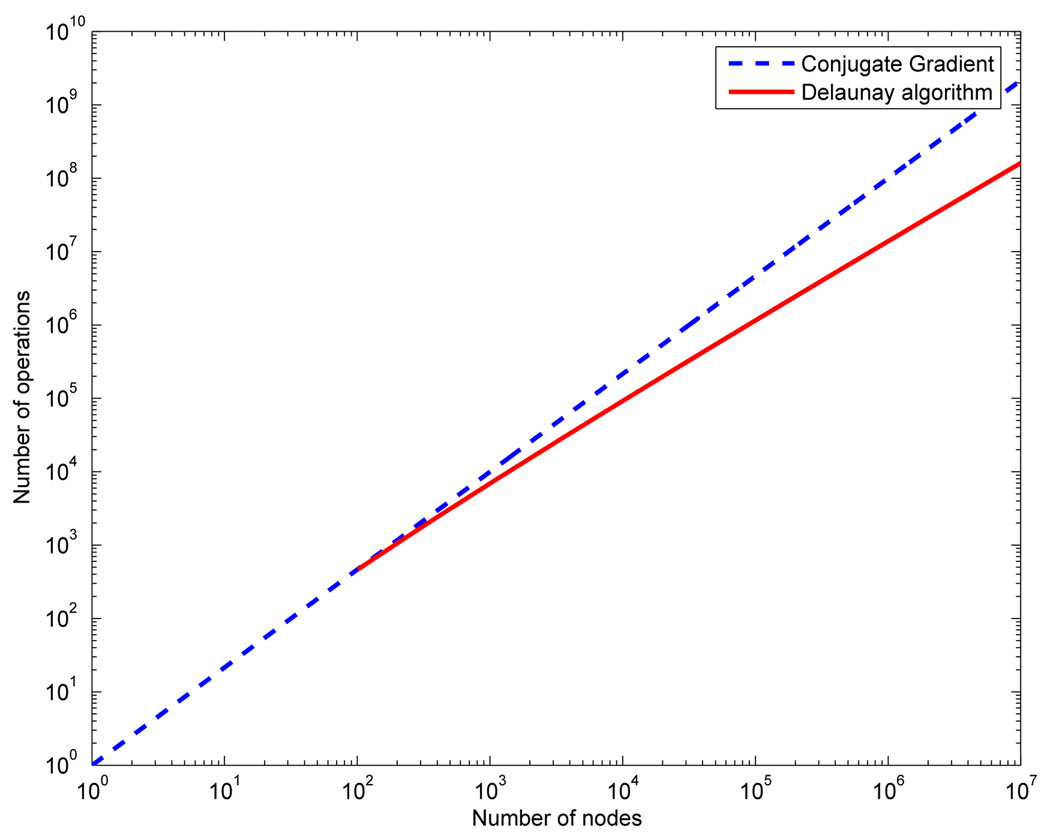
In the present work the node insertion and deletion algorithm was based on classical Delaunay methods (see [108]). With the introduction of the Watson insertion algorithm [109], the Delaunay method has become a popular option in problems that require fast re-meshing. Although Delaunay operations are conceptually simple, their robust implementation is not. Thus, the fact that the same operations may be used to both build the initial mesh and to adapt it makes Delaunay tetrahedralization attractive for a Lagrangian FSI. The term “fast re-meshing” only makes sense in the framework of an implicit solver. Indeed, Figure 12 compares the complexity of inserting n nodes in a tessellation using the Delaunay algorithm to solving a linear system (like any of the ones proposed in Equation 40–Equation 43) using an iterative method like conjugate gradients in three-dimensions. We can observe how for a large number of nodes both curves separate making the Delaunay algorithm faster than the linar algebra solver from the operation count point of view. There are other operations that add to the meshing complexity but that are common to any other meshing technique.
Figure 12.
Comparison of complexity between the Delaunay algorithm and the cojugate gradient algorithm.
3.3.4. Validation
To validate our approach to FSI, we have replicated the numerical experiments presented in [110] and compared the results with the experimental data that was generously provided to us by Dr. Stijnen. The fictitious-domain approach taken in the cited work has many merits and has been explored in many publications, e.g. [110, 23, 22, 111, 112, 14, 113]. In this manuscript we limit our simulation to the experimental configuration presented in [110] even though the solid leaflet is rigid for three reasons: 1) because those were the data that were available to us, 2) the problem is reducible to two-dimensions which gives us confidence in the experimental measurements and 3) because the problem contains contact. Following the presentation of the validation case, we present a three-dimensional solution of a neo-Hookean leaflet undergoing large deformation. No experimental data are available for this case however.
3.3.5. 2D Validation Case
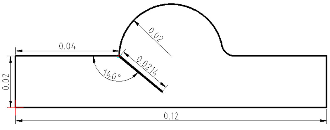
The validation simulation domain and initial angle for the leaflet are shown in Figure 13. Details of the experimental setup and data collection can be found in [110]. Here we briefly summarize the most important points. The leaflet was assigned a thickness of 0.00015 m and a density of 1000 kg/m3. Fluid properties were a density of 1000 kg/m3 and a constant viscosity of 0.0043 kg/m · s. The input flow rate to the problem is reproduced in the lower right sub-panels of Figure 14 & Figure 16. Based on the input flow profile a time varying input velocity profile was interpolated by a fourth order polynomial according to:
| (44) |
where t is the time. This velocity was applied at the left hand inlet in Figure 13. To simulate the hinge of the rigid leaflet, spring elements were placed at the pivot with a spring constant of 2.0E06 N/m. The boundary condition at the right hand side of Figure 13 consisted of imposing the pressure to a relative value.
Figure 13.
Sketch and dimensions for the aortic valve validation case.
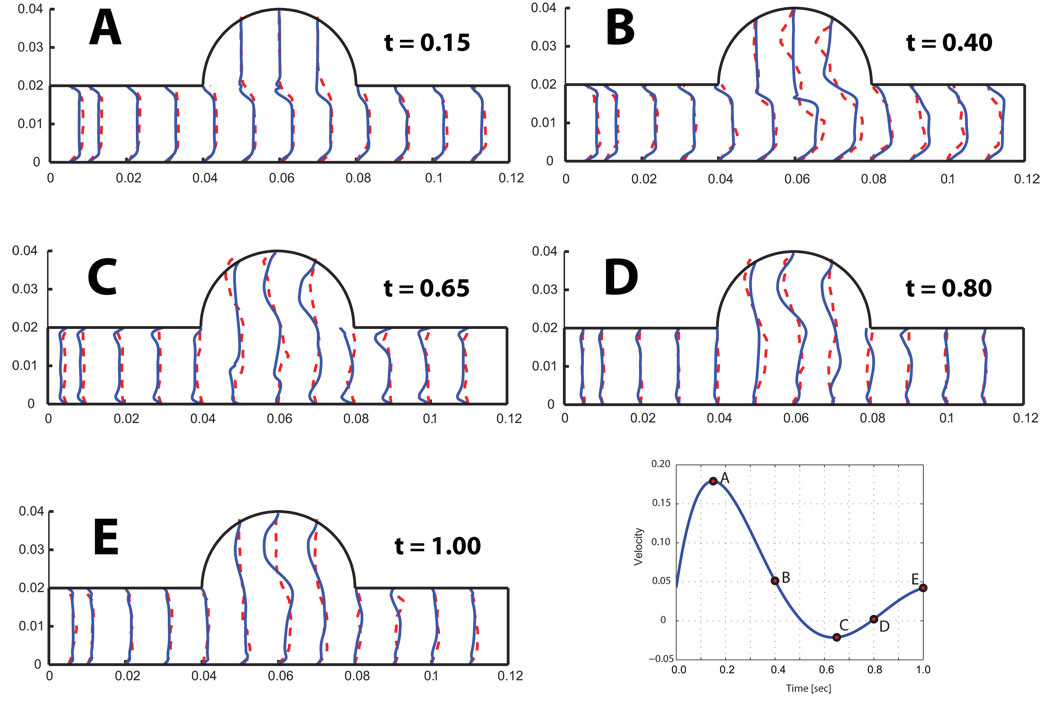
Figure 14.
Interpolated velocity profiles matched to experimental profiles at five time points labeled according to the lower right hand panel. The dashed line represents the experiment and the solid line the numerical results.
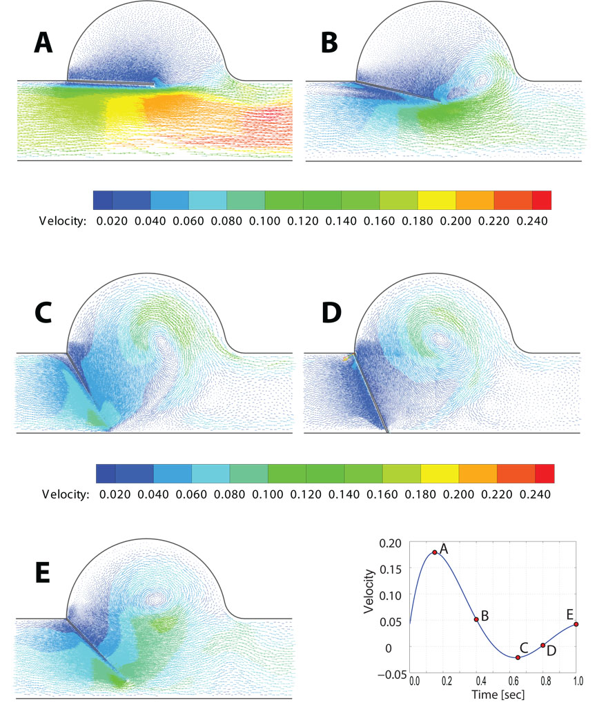
Figure 16.
Predicted velocity vector field for the 2D rigid aortic leaflet and sinus.
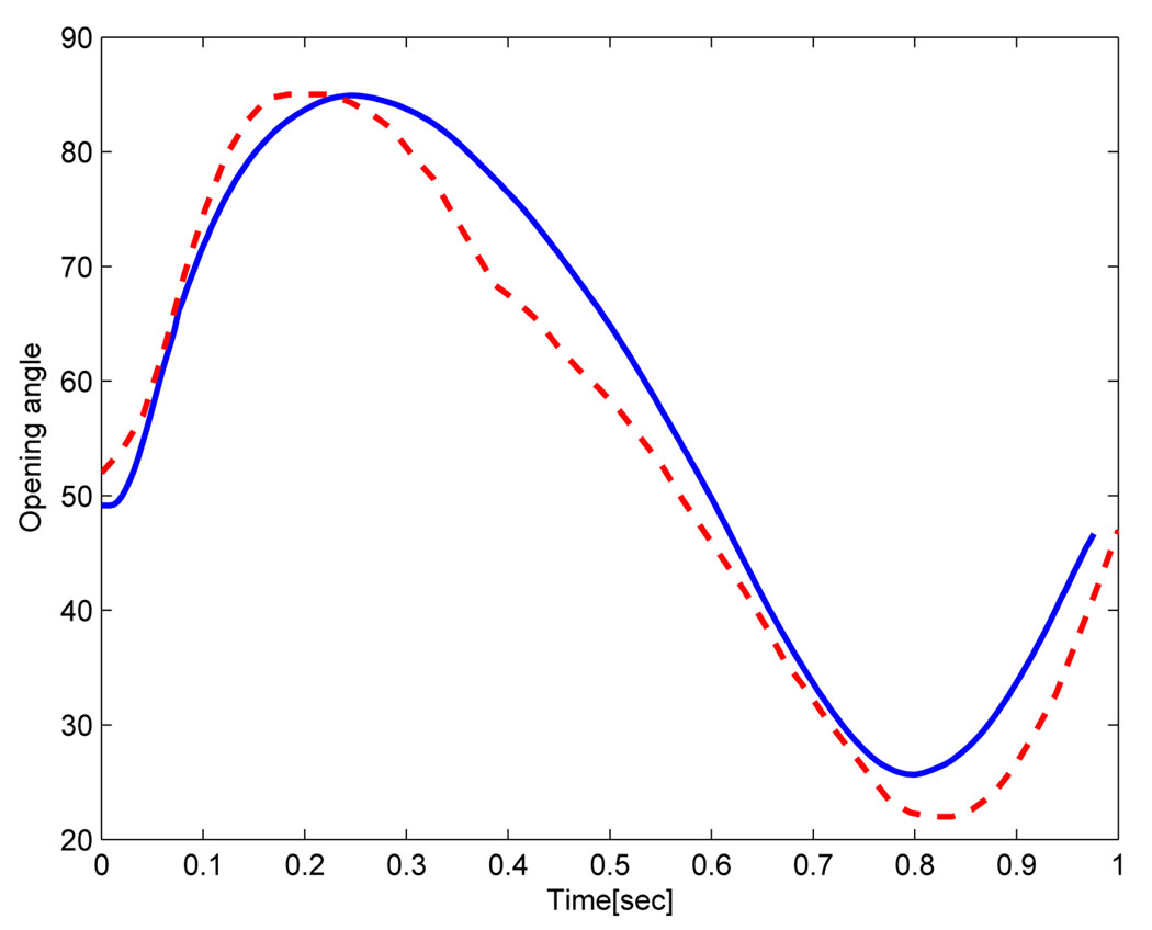
Figure 14 shows the velocity profiles at five points in time, labeled according to the graphic in the lower right hand panel. Mesh adaptivity for this example was based on keeping a constant mesh size around the leaflet. Correspondence between experimental and predicted profiles were in generally good agreement, with some notable exceptions in the aortic sinus. These differences may be due to the approximation of the inflow velocity which does not match exactly the experimental flow measure. Another source of error could be related to the model of the articulation at the top of the leaflet, where a small gap between the leaflet and the wall allows the flow to pass to the aortic sinus. Figure 15 shows the opening angle for the rigid leaflet over the course of the simulation for both model predictions and experiment. Significantly, the simulation predicted contact between the rigid leaflet and the bottom wall of the domain, as can be seen by the flat profile of the opening angle roughly between 0.7 and 0.9 seconds. This was expected. It is unclear why a similar profile is absent in the experimental data. Perhaps, experimental conditions were precisely tuned to prevent contact and the differences between simulation and experiment, such as they are, can be explained in part by slightly different initial conditions and by the manner in which the rigid pivot was achieved in our simulation. Rigid pin-joints are difficult - though not impossible - to implement in a Lagrangian framework.
Figure 15.
Computed opening angle (full line) compared to experimental results (dashed line).
In the case of real three-dimensional boundary conditions such as exist in deformable valve leaflets, this obstacle disappears, as is demonstrated in the follow-on simulation of a flexible valve leaflet in three-dimensions. Figure 16 shows the velocity vectors predicted in and around the valve sinus at the five time points labeled in the lower right graphic. These bear qualitative resemblance to the measured PIV velocity vector fields published in [110], though these specific data were not available to us so we cannot make more than a quantitative comparison.
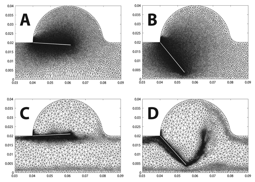
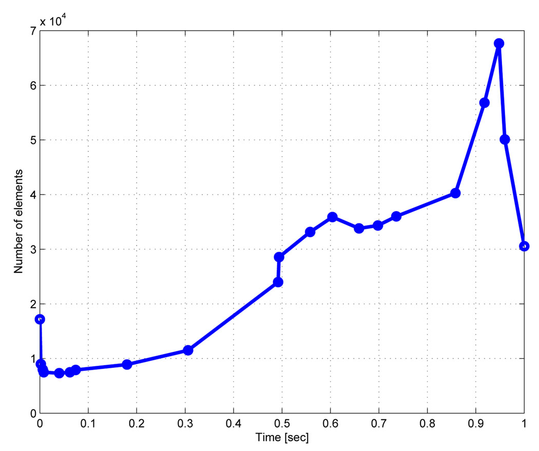
Figure 17 & Figure 18 show two cases of grid adaptivity. In the first case, a simple ad-hoc scheme was applied based on element distortion and relative size of neighbors. As can be seen, the nodal density is increased in the neighborhood of the Lagrangian leaflet, but adaptivity is excessive, resulting in large element counts. In the second case, nodal density is computed based on an a posteriori error estimate, resulting in a much more efficient addition and deletion of elements at the two time points shown in Figure 18. Throughout the simulation, the element count increased to account for the development of complex flow in the sinus and near the leaflet, increasing sharply with the onset of contact between the rigid leaflet and rigid wall. Following contact, when the solution became more quiescent and the leaflet was again open, the element count sharply decreased (Figure 19).
Figure 17.
Re-meshing step preserving the local node density around the flap for two consecutive time steps.
Figure 18.
Comparison of two re-meshing techniques as explained in section 3.3.3. In (A) and B the nodal density is kept constant throughout the computation. In (C) and D the nodal density is adapted based on a local error metric.
Figure 19.
Number of elements as a function of time for the adaptive re-meshing with an error estimate.
3.3.6. 3D neo-Hookean Leaflet
To illustrate the application of our method to a three-dimensional valve-like problem, with a deformable leaflet, we have simulated a nearly incompressible neo-Hookean flap in a cylinder. We chose the neo-Hookean model because it is nearly-incompressible, non-linear model that is a commonly used isotropic analogue for soft tissues. Specifically, the neo-Hookean model was given by
| (45) |
where S is the 2nd Piola-Kirchhoff stress, C is the Cauchy deformation, J is the Jacobian, κ is the bulk modulus, µ is the shear modulus, Īc is the first invariant of the Cauchy deformation, and DEV is the deviatoric operator, defined as
| (46) |
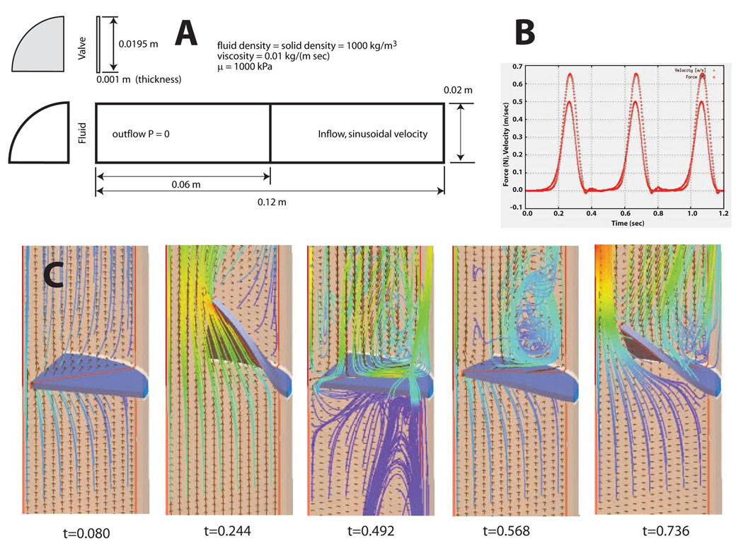
Parameters for the neo-Hookean model were κ = 2:0E06 kPa, and µ = 1000 kPa. Both the bulk modulus and the stiffness, µ are are reasonable values for an isotropic approximation to heart valve tissue. The problem domain, initial mesh and inflow velocity profile are shown in Figure 20A. The initial configuration presents a flow locking since the leaflet is completely closed and the boundary conditions at the wall are non-slip. As the incompressible flow develops the leaflet moves deforming the mesh. Element quality norms and error estimators trigger local topological mesh updates and node insertion-deletion already explained in the previous section. This kind of problem presents a challenge for ALE formulations without topological mesh modifications due to the proximity between the leaflet and the wall. Figure 20B shows the inlet velocity and the total force transmitted from the fluid to the valve as a function of time. The inflow velocity is a sinusoidal profile multiplied by an exponential function:
Figure 20.
Lagrangian fluid-structure interaction study of a large deformation, solid neo-Hookean leaflet coupled with a dynamic tetrahedral fluid grid: A) problem domain and input parameters, B) input velocity profile and transfered force, c) velocity streamlines at five points in time.
The total simulation time covers four full cycles where the valve open and closes. Figure 20C shows the velocity vectors and streamlines at five time points during simulation. It provides information about recirculation areas as well as parts of the valve that undergoes high shear stresses. The simulation was run on a laptop computer with an Intel CPU at 1.83Mhz and 2GB of RAM memory. The total computation time for 4 complete opening and closing cycles was 6.6 hours for a mesh of approximately 200K elements.
Finally it must be pointed out that this case is an idealization. At the start of valve opening a jet-like stream of fluid passes the valve. As the flow slows and valve begins to return to its starting configuration and an eddy is set up on the upstream side. These are both features observed in both chorded and non-chorded native valves. However, the bending stiffness in the isotropic flap is close to two orders of magnitude greater that of a real tissue valve. In the native aortic valve, for example, the vortices set up behind the valve in the aortic sinuses are responsible for valve closing. In addition, valve tissue is both highly non-linear and anisotropic, whereas we have presented an isotropic case. Despite these idealizations and despite the lack of experimental validation data to compare against, it does represent a good “proof of concept” example. It is a simplified geometry that allows to evaluate the strength of the algorithm in a three dimensional case.
4. Fluid-Structure Interactions in the Whole Heart: Future Challenges
4.1. Data Collection
We have successfully developed methods for processing ex-vivo magnetic resonance imaging for geometry and myofiber characterization. A larger amount of in-vivo MR data, with and without tags, will be needed to develop refined methods for strain measurement. In addition, as described above, time-dependent phase contrast data will be needed. However, the greatest development focus for the future will be needed in two principle directions: inverse analysis and 3D collagen microstructural characterization. Our approach to inverse analysis has been successful for problems characterized by a limited parameter space. It is likely that an effort to make models of cardiac structure and function that are truly predictive will require thousands, if not tens of thousands of parameters. This is problematic because in such a large parameter space, parameters are highly covariant and convergence becomes either impossible, or worse it becomes meaningless. What are needed are methods that are spatially aware. In this respect the biomedical inverse problem is not unlike inverse problems encountered in geophysics and atmospheric modeling, where automatic differentiation and its derivatives have been applied. The problem of such approaches is that they must be integrated with the FSI solver; yet open tools for their implementation do exist and continue to evolve. With regard to 3D characterization of collagen architecture, in the context of mitral ischemic regurgitation the most pressing need is to characterize the fiber orientations in the non-contractile tissue - particularly those of the mitral valve - where collagen is the dominant mechanical component. We have developed methods for histological reconstructions [114, 115, 116, 117], but our efforts must be applied to these tissues, the appropriate markers for fibrilar collagen must be identified and the algorithms for fiber connectivity must be developed.
4.2. Geometry
4.2.1. Deformable Registration
In order to resolve the mitral leaflets and chordae in the ventricle, we must image an ex-vivo heart. This is problematic since the heart is subject to multiple deformations upon excision from the chest due to fixation, handling, gravity and lack of confinement. In short, the ex-vivo geometry is different from the in-vivo geometry. We propose to solve this problem by solving a nonlinear deformable registration problem between the high-resolution ex-vivo (source) dataset and a lower resolution in-vivo (target) dataset, the solution of which would be high-resolution deformation field. The proposed approach follows an affine transformation based on landmarks with a non-affine approach based on discrete labeling and linear programming, wherein the registration is redefined as a minimal path extraction in a weighted graph [118, 119]. This work is ongoing.
4.3. Lagrangian FSI
A fluid-structure interaction study of the whole heart or even just the left heart in support of an investigation of surgical interventions to correct mitral ischemic regurgitation will be a computationally intensive effort, albeit one that will open new avenues in cardiac research. In this manuscript, we have presented a new Lagrangian segregated scheme for biofluid-structure interactions that has excellent convergence properties that make it well suited to the task. In addition, contact, once thought to be the stumbling block for the Lagrangian approach, has been addressed. Clearly, the scheme will have to be parallelized to run on massively parallel architectures. An advantage of adopting a segregated scheme is that parallelism can be handled separately for fluid and solid domains. This is a clear advantage as the continuum structural solver has already been parallelized and already scales quite well. Efforts are currently underway to parallelize the linear algebra developed in Section 3.3.2. However, a similar effort will have to be made to parallelize the mesh adaption operations. Currently, these only account for roughly 10% of the solution time. With the linear algebra parallelized this percentage may be become a bottleneck. We are investigating strategies toward this aim. Another clear challenge towards good scalability is the development of an efficient contact algorithm in the framework of Lagrangian FSI, where load balancing will require a new mesh partition in the fluid as well as in the solid domain.
4.4. Validation
In this manuscript, we have presented a simple 2D validation of our approach to Lagrangian FSI, by comparing model predictions with experimental data. The task of validating simulations of the left heart with mitral valve will be monumentally more difficult, but are critical. Despite our fidelity to imaging-based geometry and microstructural data, many simplifications will necessarily be introduced to the problem. Not the least of these is how to account for boundary conditions represented by cardiac motion, sure to have an impact on fluid flow, and how to account for truncations of the computational domain. Validations for FSI simulations of the left heart will need to be to be of two kinds. First, we will need to acquire phase contrast velocity data to validate blood flow predictions. Here it will be necessary to register 3D measured velocity vectors with computational predictions. Second, we will need to measure and compare myocardial strain with predicted strains and predictions. The current state of the art for dynamic myocardial strain measurements is based on magnetic resonance tagging, and is an approach that we have used successfully in the past [120, 121, 10]. However MR tagging does have limitations, not least of which are necessary manual interaction, uncertainty whether material points move orthogonally to the imaging plane and limited resolution. We are currently investigating the use of optical flow to overcome these limitations. Due to resolution limitations of MR and even echo, in-vivo valvular motion and strain are more difficult. The data provided by Dr. Stijnen and his colleagues are invaluable, but three-dimensional in-vitro flow, deformation and strain data with a native mitral valve are sorely needed.
5. Conclusions
In this manuscript we have presented a comprehensive strategy for carrying out a predictive analysis of mitral ischemic regurgitation. From a description of our early work, we have described our current work in the areas of data collection, geometry, fluid-structure interactions and validation. Our efforts are integrated. Thus, for example, our grid generation algorithms were developed in support of a Lagrangian approach to FSI. The strategies for image analysis, data analyses and mapping were all driven by a recognition that imaging based approaches were necessary to bring together efforts to model both mitral valve and left ventricle in a predictive framework.
A novel approach for Lagrangian FSI was also introduced and applied to a benchmark problem with experimental results and to a 3D problem where large deformations occur. The CSD solver and the CFD solver were coupled through a Laplace matrix computed on the interface that provides good stability for problems that show added mass effects. The fully Lagrangian interface allows the exact imposition of boundary conditions and provides a path towards boundary layer meshing, a difficult task for embedded or immersed interface methods. The algorithm is complemented by adaptive meshing based on an a posteriori error metric. Good agreement was observed between the numerical model and the experimental results. The ability of the method to handle contact was also evident, which is a fundamental requirement for any numerical technique applied to cardiovascular problems.
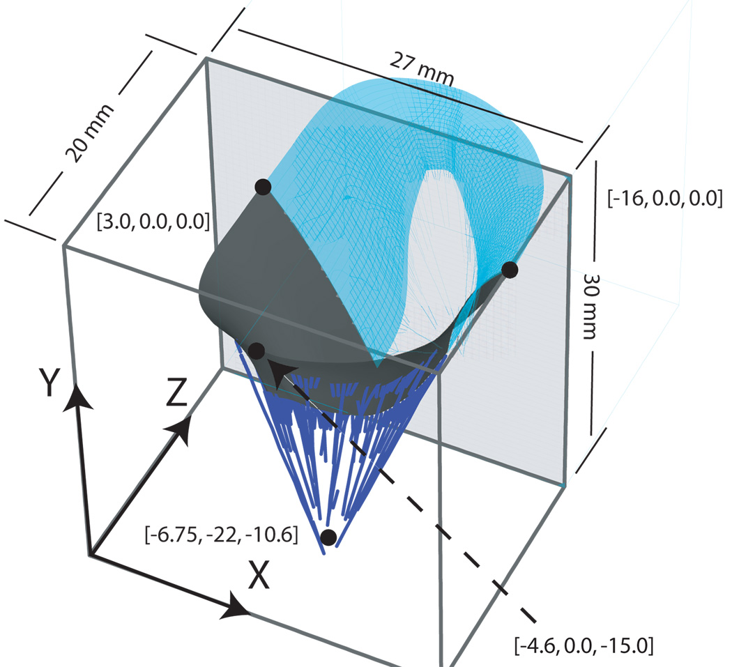
Figure 1.
Axisymmetric geometry of the fluid-coupled mitral valve model. The fluid-domain was modeled as an Eulerian box. Pressure curves were applied to the atrial and ventricular surfaces. The model was axisymmetric; the half indicated by the light blue shading was not modeled.
Acknowledgments
Research funded by the National Heart and Blood Institute Awards 5R01HL077921-03 and 1R01-HL084431-01A1 and 1RO1-HL073598-01A.
REFERENCES
- 1.Peskin CS. Flow patterns around heart valves: a numerical method. J Comnp Phys. 1972;10:252–271. [Google Scholar]
- 2.Cheng Y, Oertel H, Schenkel T. Fluid-structure coupled CFD simulation of the left ventricular flow during filling phase. Ann Biomed Eng. 2005;33(5):567–576. doi: 10.1007/s10439-005-4388-9. [DOI] [PubMed] [Google Scholar]
- 3.Lemmon JD, Yoganathan AP. Three-dimensional computational model of left heart diastolic function with fluid-structure interaction. J Biomech Eng. 2000;122(2):109–117. doi: 10.1115/1.429648. [DOI] [PubMed] [Google Scholar]
- 4.Redaelli A, Montevecchi FM. Computational evaluation of intraventricular pressure gradients based on a fluid-structure approach. J Biomech Eng. 1996;118(4):529–537. doi: 10.1115/1.2796040. [DOI] [PubMed] [Google Scholar]
- 5.Watanabe H, Sugiura S, Kafuku H, Hisada T. Multiphysics simulation of left ventricular filling dynamics using fluid-structure interaction finite element method. Biophys J. 2004;87(3):2074–2085. doi: 10.1529/biophysj.103.035840. [DOI] [PMC free article] [PubMed] [Google Scholar]
- 6.Redaelli A, Maisano F, Schreuder JJ, Montevecchi FM. Ventricular motion during the ejection phase: a computational analysis. J Appl Physiol. 2000;89(1):314–322. doi: 10.1152/jappl.2000.89.1.314. [DOI] [PubMed] [Google Scholar]
- 7.Carmody CJ, Burriesci G, Howard IC, Patterson EA. An approach to the simulation of fluid-structure interaction in the aortic valve. J Biomech. 2006;39(1):158–169. doi: 10.1016/j.jbiomech.2004.10.038. [DOI] [PubMed] [Google Scholar]
- 8.Tang D, Yang C, Geva T, del Nido PJ. Two-layer passive/active anisotropic FSI models with fiber orientation: MRI-based patient-specific modeling of right ventricular response to pulmonary valve insertion surgery. Mol Cell Biomech. 2007;4(3):159–176. [PubMed] [Google Scholar]
- 9.Tang D, Yang C, Geva T, Del Nido PJ. Patient-specific MRI-based 3D FSI RV/LV/patch models for pulmonary valve replacement surgery and patch optimization. J Biomech Eng. 2008;130(4):041010. doi: 10.1115/1.2913339. [DOI] [PMC free article] [PubMed] [Google Scholar]
- 10.Walker JC, Ratcliffe MB, Zhang P, Wallace AW, Hsu EW, Saloner DA, Guccione JM. Magnetic resonance imaging-based finite element stress analysis after linear repair of left ventricular aneurysm. J Thorac Cardiovasc Surg. 2008;135(5):1094–1102. e1–e2. doi: 10.1016/j.jtcvs.2007.11.038. [DOI] [PMC free article] [PubMed] [Google Scholar]
- 11.Wall ST, Walker JC, Healy KE, Ratcliffe MB, Guccione JM. Theoretical impact of the injection of material into the myocardium: a finite element model simulation. Circulation. 2006;114(24):2627–2635. doi: 10.1161/CIRCULATIONAHA.106.657270. [DOI] [PubMed] [Google Scholar]
- 12.Nickerson D, Niederer S, Stevens C, Nash M, Hunter P. A computational model of cardiac electromechanics. Conf Proc IEEE Eng Med Biol Soc. 2006;1:5311–5314. doi: 10.1109/IEMBS.2006.260169. [DOI] [PubMed] [Google Scholar]
- 13.Kerckhoffs RC, Neal ML, Gu Q, Bassingthwaighte JB, Omens JH, McCulloch AD. Coupling of a 3D finite element model of cardiac ventricular mechanics to lumped systems models of the systemic and pulmonic circulation. Ann Biomed Eng. 2007;35(1):1–18. doi: 10.1007/s10439-006-9212-7. [DOI] [PMC free article] [PubMed] [Google Scholar]
- 14.De Hart J, Peters GW, Schreurs PJ, Baaijens FP. A three-dimensional computational analysis of fluid-structure interaction in the aortic valve. J Biomech. 2003;36(1):103–112. doi: 10.1016/s0021-9290(02)00244-0. [DOI] [PubMed] [Google Scholar]
- 15.Dumont K, Stijnen JM, Vierendeels J, van de Vosse FN, Verdonck PR. Validation of a fluid-structure interaction model of a heart valve using the dynamic mesh method in fluent. Comput Methods Biomech Biomed Engin. 2004;7(3):139–146. doi: 10.1080/10255840410001715222. [DOI] [PubMed] [Google Scholar]
- 16.Guivier C, Deplano V, Pibarot P. New insights into the assessment of the prosthetic valve performance in the presence of subaortic stenosis through a fluid-structure interaction model. J Biomech. 2007;40(10):2283–2290. doi: 10.1016/j.jbiomech.2006.10.010. [DOI] [PubMed] [Google Scholar]
- 17.Kaminsky R, Dumont K, Weber H, Schroll M, Verdonck P. PIV validation of blood-heart valve leaflet interaction modelling. Int J Artif Organs. 2007;30(7):640–648. doi: 10.1177/039139880703000712. [DOI] [PubMed] [Google Scholar]
- 18.Makhijani VB, Yang HQ, Dionne PJ, Thubrikar MJ. Three-dimensional coupled fluid-structure simulation of pericardial bioprosthetic aortic valve function. Asaio J. 1997;43(5):M387–M392. [PubMed] [Google Scholar]
- 19.Morsi YS, Yang WW, Wong CS, Das S. Transient fluid-structure coupling for simulation of a trileaflet heart valve using weak coupling. J Artif Organs. 2007;10(2):96–103. doi: 10.1007/s10047-006-0365-9. [DOI] [PubMed] [Google Scholar]
- 20.Nicosia MA, Cochran RP, Einstein DR, Rutland CJ, Kunzelman KS. A coupled fluid-structure finite element model of the aortic valve and root. J Heart Valve Dis. 2003;12(6):781–789. [PubMed] [Google Scholar]
- 21.Weinberg EJ, Kaazempur Mofrad MR. Transient, three-dimensional, multiscale simulations of the human aortic valve. Cardiovasc Eng. 2007;7(4):140–155. doi: 10.1007/s10558-007-9038-4. [DOI] [PubMed] [Google Scholar]
- 22.van de Vosse FN, van Loon R, Anderson PD. A fluid-structure interaction method with solid-rigid contact for heart valve dynamics. J. Comput. Phys. 2006;217(2):806–823. [Google Scholar]
- 23.van Loon R, Anderson PD, de Hart J, Baaijens FPT. A combined fictitious domain/adaptive meshing method for fluid-structure interaction in heart valves. Int. J. Numer. Meth. Fluids. 2004;46(5):533–544. [Google Scholar]
- 24.Watton PN, Luo XY, Wang X, Bernacca GM, Molloy P, Wheatley DJ. Dynamic modelling of prosthetic chorded mitral valves using the immersed boundary method. J Biomech. 2007;40(3):613–626. doi: 10.1016/j.jbiomech.2006.01.025. [DOI] [PubMed] [Google Scholar]
- 25.Einstein DR, Kunzelman KS, Reinhall PG, Nicosia MA, Cochran RP. Non-linear fluid-coupled computational model of the mitral valve. J Heart Valve Dis. 2005;14(3):376–385. [PubMed] [Google Scholar]
- 26.Watton P, Luo XY, Yin M, Bernacca GM, Wheatley DJ. Effect of ventricle motion on the dynamic behaviour of chorded mitral valves. J. of Fluids and Structures. 2008;24:58–74. [Google Scholar]
- 27.Thubrikar M, Piepgrass WC, Shaner TW, Nolan SP. The design of the normal aortic valve. Am J Physiol. 1981;241(6):H795–H801. doi: 10.1152/ajpheart.1981.241.6.H795. [DOI] [PubMed] [Google Scholar]
- 28.Grande-Allen KJ, Cochran RP, Reinhall PG, Kunzelman KS. Re-creation of sinuses is important for sparing the aortic valve: a finite element study. J Thorac Cardiovasc Surg. 2000;119(4 Pt 1):753–763. doi: 10.1016/S0022-5223(00)70011-0. [DOI] [PubMed] [Google Scholar]
- 29.Kunzelman KS, Cochran RP, Chuong C, Ring WS, Verrier ED, Eberhart RD. Finite element analysis of the mitral valve. J Heart Valve Dis. 1993;2(3):326–340. [PubMed] [Google Scholar]
- 30.Votta E, Caiani E, Veronesi F, Soncini M, Montevecchi FM, Redaelli A. Mitral valve finite-element modelling from ultrasound data: a pilot study for a new approach to understand mitral function and clinical scenarios. Phil. Trans. R. Soc. 2008;366:3411–3434. doi: 10.1098/rsta.2008.0095. [DOI] [PubMed] [Google Scholar]
- 31.Pierard LA, Lancellotti P. The role of ischemic mitral regurgitation in the pathogenesis of acute pulmonary edema. N Engl J Med. 2004;351(16):1627–1634. doi: 10.1056/NEJMoa040532. [DOI] [PubMed] [Google Scholar]
- 32.White HD, Norris RM, Brown MA, Brandt PW, Whitlock RM, Wild CJ. Left ventricular end-systolic volume as the major determinant of survival after recovery from myocardial infarction. Circulation. 1987;76(1):44–51. doi: 10.1161/01.cir.76.1.44. [DOI] [PubMed] [Google Scholar]
- 33.Kunzelman KS, Einstein DR, Cochran RP. Fluid-structure interaction models of the mitral valve: function in normal and pathological states. Philos Trans R Soc Lond B Biol Sci. 2007;362(1484):1393–1406. doi: 10.1098/rstb.2007.2123. [DOI] [PMC free article] [PubMed] [Google Scholar]
- 34.Einstein DR, Kunzelman KS, Reinhall PG, Nicosia MA, Cochran RP. The relationship of normal and abnormal microstructural proliferation to the mitral valve closure sound. J Biomech Eng. 2005;127(1):134–147. doi: 10.1115/1.1835359. [DOI] [PubMed] [Google Scholar]
- 35.Einstein DR, Kunzelman KS, Reinhall PG, Cochran RP, Nicosia MA. Haemodynamic determinants of the mitral valve closure sound: a finite element study. Med Biol Eng Comput. 2004;42(6):832–846. doi: 10.1007/BF02345218. [DOI] [PubMed] [Google Scholar]
- 36.Cochran RP, Kunzelman KS, Chuong CJ, Sacks MS, Eberhart RC. Nondestructive analysis of mitral valve collagen fiber orientation. ASAIO Trans. 1991;37(3):M447–M448. [PubMed] [Google Scholar]
- 37.May-Newman K, Yin FC. Biaxial mechanical behavior of excised porcine mitral valve leaflets. Am. J. Physiol. 1995;269(4 Pt 2):H1319–H1327. doi: 10.1152/ajpheart.1995.269.4.H1319. [DOI] [PubMed] [Google Scholar]
- 38.May-Newman K, Yin FC. A constitutive law for mitral valve tissue. J. Biomech. Eng. 1998;120(1):38–47. doi: 10.1115/1.2834305. [DOI] [PubMed] [Google Scholar]
- 39.Kunzelman KS, Cochran RP, Verrier ED, Eberhardt RC. Anatomic basis for mitral valve modeling. Journal of Heart Valve Disease. 1994;3:491–496. [PubMed] [Google Scholar]
- 40.Salisbury PF, Cross CE, Rieben PA. Chorda tendinae tension. Americal Journal of Physiology. 1962;205(2):385–392. doi: 10.1152/ajplegacy.1963.205.2.385. [DOI] [PubMed] [Google Scholar]
- 41.Komeda M, Glasson JR, Bolger AF, Daughters GT, Niczyporuk MA, Ingels NB, Miller DC. Three-dimensional dynamic geometry of the normal canine mitral annulus and papillary muscles. Circulation. 1996;94(9) Supplement:159–163. [PubMed] [Google Scholar]
- 42.Dagum P, Timek TA, Green GR, Lai D, Daughters GT, Liang DH, Hayase M, Ingels NB, Miller DC. Coordinate-free analysis of mitral valve dynamics in normal and iscemic hearts. Circulation. 2000;102 Suppl-III:62–69. doi: 10.1161/01.cir.102.suppl_3.iii-62. [DOI] [PubMed] [Google Scholar]
- 43.Komeda M, Glasson JR, Bolger AF, Daughters GT, Ingels NB, Miller DC. Papillary muscle-left ventricular wall "complex". Journal of Thoracic and Cardiovascular Surgery. 1997;113(2):292–301. doi: 10.1016/s0022-5223(97)70326-x. [DOI] [PubMed] [Google Scholar]
- 44.Reimink MS, Kunzelman KS, Verrier ED, Cochran RP. The effect of anterior chordal replacement on mitral valve function and stresses. a finite element study. Asaio J. 1995;41(3):M754–M762. doi: 10.1097/00002480-199507000-00114. [DOI] [PubMed] [Google Scholar]
- 45.Reimink MS, Kunzelman KS, Cochran RP. The effect of chordal replacement suture length on function and stresses in repaired mitral valves: a finite element study. J Heart Valve Dis. 1996;5(4):365–375. [PubMed] [Google Scholar]
- 46.Cochran RP, Kunzelman KS. Effect of papillary muscle position on mitral valve function: relationship to homografts. Ann Thorac Surg. 1998;66(6 Suppl):S155–S161. doi: 10.1016/s0003-4975(98)01100-x. [DOI] [PubMed] [Google Scholar]
- 47.Benson DJ. Computational methods in lagrangian and eulerian hydrocodes. Computer Methods Applied Mechanics and Engineering. 1992;99:235–394. [Google Scholar]
- 48.Benson DJ. Momentum advection on a staggered mesh. J. Computational Phys. 1992;100:143–162. [Google Scholar]
- 49.Souli M. An eulerian and fluid-structure coupling algorithm in LS-DYNA. Emerging Technologies in Fluids, Structures and Fluid/Structure Interactions, ASME. 1999;volume 396 [Google Scholar]
- 50.Jensen KT, Fontaine A, Yoganathan AP. Improved in vitro quantification of the force exerted by the papillary muscle on the left ventricular wall: three-dimensional force vector measurement system. Ann Biomed Eng. 2001;29(5):406–413. doi: 10.1114/1.1366672. [DOI] [PubMed] [Google Scholar]
- 51.Blick EF, Sabbah HN, Stein PD. One-dimensional model of diastolic semilunar valve vibrations productive of heart sounds. Journal of Biomechanics. 1979;12:223–227. doi: 10.1016/0021-9290(79)90145-3. [DOI] [PubMed] [Google Scholar]
- 52.Genest J, Durand LG. Relationship of the left ventricular and apical first sounds to the left ventricular derivative. Med Biol Eng Comput. 1985;23:95–98. doi: 10.1007/BF02444038. [DOI] [PubMed] [Google Scholar]
- 53.Harvey WP. Cardiac pearls. Dis Mon. 1994;40(2):41–113. doi: 10.1016/0011-5029(94)90002-7. [DOI] [PubMed] [Google Scholar]
- 54.Perloff JK. Cardiac auscultation. Dis Mon. 1980;26(9):1–47. doi: 10.1016/s0011-5029(80)80009-5. [DOI] [PubMed] [Google Scholar]
- 55.Sakamoto T. So-called "apical" systolic murmur of mitral regurgitation is not "apical". J Cardiol. 1995;25(6):329–334. [PubMed] [Google Scholar]
- 56.Hashim SR, Fontaine A, Shengqui He, Levine RA, Yoganathan AJ. A three-component force vector cell for in vitro quantification of force exerted by the papillary muscle on the left ventricular wall. Journal of Biomechanics. 1997;30(10):1071–1075. doi: 10.1016/s0021-9290(97)00066-3. [DOI] [PubMed] [Google Scholar]
- 57.Nielsen RA, Nygaard H, Fontaine A. Chordal force distribution determines systolic mitral leaflet configuration and severity of functional mitral regurgitation. J. Am. Coll. Cardiol. 1999;33:843–853. doi: 10.1016/s0735-1097(98)00627-5. [DOI] [PubMed] [Google Scholar]
- 58.Moussou P. A kinematic method for the computation of the natural modes of fluid-structure interaction systems. Journal of fluids and structures. 2005;20(10):643–658. [Google Scholar]
- 59.Lorensen WE, Cline HE. Marching cubes: A high resolution 3d surface construction algorithm. Computer Graphics. 1987;21:163–169. [Google Scholar]
- 60.Walker JC, Guccione JM, Jiang Y, Zhang P, Wallace AW, Hsu EW, Ratcliffe MB. Helical myofiber orientation after myocardial infarction and left ventricular surgical restoration in sheep. J Thorac Cardiovasc Surg. 2005;129(2):382–390. doi: 10.1016/j.jtcvs.2004.06.006. [DOI] [PubMed] [Google Scholar]
- 61.Kuprat AP, Mosso SJ. Technical report, Los Alamos National Laboratory; Efficient algorithms for mapping cell quantities between overlapped 3-d unstructured meshes. 2005 Technical Report LA-UR-05-5084.
- 62.Jiang Y, Guccione JM, Ratcliffe MB, Hsu EW. Transmural heterogeneity of diffusion anisotropy in the sheep myocardium characterized by mr diffusion tensor imaging. Am J Physiol Heart Circ Physiol. 2007;293(4):H2377–H2384. doi: 10.1152/ajpheart.00337.2007. [DOI] [PubMed] [Google Scholar]
- 63.Anderson RH, Sanchez-Quintana D, Niederer P. Structural-functional correlates of the 3-dimensional arrangement of myocytes making up the ventricular walls. J. Thorac. Cardiovac. Surg. 2008;136(1):10–18. doi: 10.1016/j.jtcvs.2007.09.083. [DOI] [PubMed] [Google Scholar]
- 64.Einstein DR, Freed AD, Stander N, Fata B, Vesely I. Inverse parameter fitting of biological tissues: a response surface approach. Ann Biomed Eng. 2005;33(12):1819–1830. doi: 10.1007/s10439-005-8338-3. [DOI] [PubMed] [Google Scholar]
- 65.Chen K, Fata B, Einstein DR. Characterization of the highly nonlinear and anisotropic vascular tissues from experimental inflation data: A validation study toward the use of clinical data for in-vivo modeling and analysis. Ann Biomed Eng. 2008 doi: 10.1007/s10439-008-9541-9. [DOI] [PMC free article] [PubMed] [Google Scholar]
- 66.Roux WJ, Stander N, Haftka RT. Response surface approximations for structural optimization. Int. J. Num. Meth. Eng. 1998;42:517–534. [Google Scholar]
- 67.Stander N. On the robustness of a simple domain reduction scheme for simulation-based optimization. Engineering Computations. 2002;19(4):431–450. [Google Scholar]
- 68.Myers RH. Response surface methodology : process and product optimization using designed experiments. Wiley; 2002. [Google Scholar]
- 69.Guccione JM, Waldman LK, McCulloch AD. Mechanics of active contraction in cardiac muscle: Part ii–cylindrical models of the systolic left ventricle. J Biomech Eng. 1993;115(1):82–90. doi: 10.1115/1.2895474. [DOI] [PubMed] [Google Scholar]
- 70.Kuprat AP, Einstein DR. An anisotropic scale-invariant unstructured mesh generator suitable for volumetric imaging data. J. Comput. Phys. 2008 doi: 10.1016/j.jcp.2008.09.030. [DOI] [PMC free article] [PubMed] [Google Scholar]
- 71.Dyedov V, Einstein DR, Jiao X, Kuprat AP, Carson JP, del Pin F. Variational generation of prismatic boundary-layer meshes. Int. J. Numer. Meth. Engrg. 2008 doi: 10.1002/nme.2583. in Press. [DOI] [PMC free article] [PubMed] [Google Scholar]
- 72.Jiao X. Face offsetting: A unified approach for explicit moving interfaces. J. Comput. Phys. 2007;220:612–625. [Google Scholar]
- 73.Lorensen WE, Cline HE. Marching cubes: A high resolution 3-d surface construction algorithm. Computer Graphics. 1987 July;21(4):163–170. [Google Scholar]
- 74.Newman TS, Yi H. A survey of the marching cubes algorithm. Computers & Graphics. 2006;30:854–879. [Google Scholar]
- 75.Jiao X, Zha H. Consistent computation of first- and second-order differential quantities for surface meshes; ACM Solid and Physical Modeling Symposium; 2008. [Google Scholar]
- 76.Amenta N, Bern M. Surface reconstruction by Voronoi filtering. Discr. and Comp. Geom. 1999;22:481–504. [Google Scholar]
- 77.Smits B. Efficiency issues for ray tracing. SIGGRAPH ’05: ACM SIGGRAPH 2005 Courses. 2005:6. http://doi.acm.org/10.1145/1198555.1198745.
- 78.Khamayseh A, Hansen G. Use of the spatial kD-tree in computational physics applications. Commun. Comput. Phys. 2007;2:545–576. [Google Scholar]
- 79.Zarins CK, Taylor CA, Hughes TJR. Finite element modeling of blood flow in arteries. Comput. Methods Appl. Mech. Engrg. 1998;158:155–196. [Google Scholar]
- 80.Longest WP. Comparison of blood particle deposition models for non-parallel flow domains. J. Biomech. 2003;36(3):421–430. doi: 10.1016/s0021-9290(02)00434-7. [DOI] [PubMed] [Google Scholar]
- 81.Chiou MC. Particle deposition from natural convection boundary layer flow onto an isothermal vertical cylinder. Acta Mechanica. 1998;129:1619–6937. [Google Scholar]
- 82.Kroger C, Drossinos Y. Particle deposition in a turbulent boundary layer over a large particle size spectrum. J. Aerosol Sci. 1997;28:631–632. [Google Scholar]
- 83.Sethian JA. Level Set Methods and Fast Marching Methods: Evolving Interfaces in Computational Geometry, Fluid Mechanics, Computer Vision, and Materials Science. Cambridge University Press; 1999. [Google Scholar]
- 84.Si H. Adaptive tetrahedral mesh generation by constrained Delaunay refinement. Int. J. Numer. Meth. Engrg. 2008 http://dx.doi.org/10.1002/nme.2318.
- 85.Zhang Y, Bajaj C. Finite element meshing for cardiac analysis. Technical report, the University of Texas at Austin; 2004. Technical Report 04-26. [Google Scholar]
- 86.Zhang Y, Bajaj C, Sohn B-S. 3d finite element meshing from imaging data. Computer Methods in Applied Mechanics and Engineering. 2005;194:5083–5106. doi: 10.1016/j.cma.2004.11.026. [DOI] [PMC free article] [PubMed] [Google Scholar]
- 87.Cattaruzza M, Guzik TJ, Slodowski W, Pelvan A, Becker J, Halle M, Buchwald AB, Channon KM, Hecker M. Shear stress insensitivity of endothelial nitric oxide synthase expression as a genetic risk factor for coronary heart disease. Circ Res. 2004;95(8):841–847. doi: 10.1161/01.RES.0000145359.47708.2f. [DOI] [PubMed] [Google Scholar]
- 88.Chen LC, Nadziejko C. Effects of subchronic exposures to concentrated ambient particles (CAPs) in mice. V. CAPs exacerbate aortic plaque development in hyperlipidemic mice. Inhal Toxicol. 2005;17(4–5):217–224. doi: 10.1080/08958370590912815. [DOI] [PubMed] [Google Scholar]
- 89.Chien S, Li S, Shiu YT, Li YS. Molecular basis of mechanical modulation of endothelial cell migration. Front Biosci. 2005;10:1985–2000. doi: 10.2741/1673. [DOI] [PubMed] [Google Scholar]
- 90.Cummins PM, Cotter EJ, Cahill PA. Hemodynamic regulation of metallopeptidases within the vasculature. Protein Pept Lett. 2004;11(5):433–442. doi: 10.2174/0929866043406580. [DOI] [PubMed] [Google Scholar]
- 91.Dardik A, Yamashita A, Aziz F, Asada H, Sumpio BE. Shear stress-stimulated endothelial cells induce smooth muscle cell chemotaxis via platelet-derived growth factor-BB and interleukin-1 alpha. J Vasc Surg. 2005;41(2):321–331. doi: 10.1016/j.jvs.2004.11.016. [DOI] [PubMed] [Google Scholar]
- 92.Ganguli A, Persson L, Palmer IR, Evans I, Yang L, Smallwood R, Black R, Qwarnstrom EE. Distinct NF-kappaB regulation by shear stress through ras-dependent IkappaBalpha oscillations: real-time analysis of flow-mediated activation in live cells. Circ Res. 2005;96(6):626–634. doi: 10.1161/01.RES.0000160435.83210.95. [DOI] [PubMed] [Google Scholar]
- 93.Butcher JT, Markwald RR. Valvulogenesis: the moving target. Philos Trans R Soc Lond B Biol Sci. 2007;362(1484):1489–1503. doi: 10.1098/rstb.2007.2130. [DOI] [PMC free article] [PubMed] [Google Scholar]
- 94.Butcher JT, Nerem RM. Valvular endothelial cells and the mechanoregulation of valvular pathology. Philos Trans R Soc Lond B Biol Sci. 2007;362(1484):1445–1457. doi: 10.1098/rstb.2007.2127. [DOI] [PMC free article] [PubMed] [Google Scholar]
- 95.Butcher JT, Tressel S, Johnson T, Turner D, Sorescu G, Jo H, Nerem RM. Transcriptional profiles of valvular and vascular endothelial cells reveal phenotypic differences: influence of shear stress. Arterioscler Thromb Vasc Biol. 2006;26(1):69–77. doi: 10.1161/01.ATV.0000196624.70507.0d. [DOI] [PubMed] [Google Scholar]
- 96.Idelsohn SR, Oñate E, Calvo N, Del Pin F. The meshless finite element method. Int. J. Numer. Meth. Engrg. 2003;58:893–912. [Google Scholar]
- 97.Idelsohn SR, Oñate E, Del Pin F. A lagrangian meshless finite element method applied to fluid-structure interaction problems. Computers & Structures. 2003;82:655–671. [Google Scholar]
- 98.Idelsohn SR, Oñate E, Del Pin F. The particle finite element method a powerful tool to solve incompressible flows with free-surfaces and breaking waves. Int. J. Numer. Meth. Engrg. 2004;61:964–984. [Google Scholar]
- 99.Aubry R, Idelsohn SR, Oñate E. Particle finite element method in fluid mechanics including thermal convection-diffusion. Computer & Structures. 2004;83:1459–1475. [Google Scholar]
- 100.Del Pin F, Idelsohn SR, Oñate E, Aubry R. The ALE/lagrangian particle finite element method: A new approach to computation of free-surface flows and fluid-object interactions. Computers & Fluids. 2007;36:27–38. [Google Scholar]
- 101.Idelsohn SR, Oñate E, Marti J, Rossi R. Fluid-structure interacion problems including ”added-mass effect”; 8th. World Congress on Computational Mechanics; Venice, Italy. 2008. [Google Scholar]
- 102.Freed AD, Einstein DR, Vesely I. Invariant formulation for dispersed transverse isotropy in aortic heart valves: an efficient means for modeling fiber splay. Biomech Model Mechanobiol. 2005;4(2–3):100–117. doi: 10.1007/s10237-005-0069-8. [DOI] [PubMed] [Google Scholar]
- 103.Badia S, Codina R. Pressure segregation methods based on a discrete pressure poisson equation. an algebraic approach. Int. J. Numer. Meth. Fluids. 2007;56:351–382. [Google Scholar]
- 104.Codina R. Stabilization of incompressibility and convection through orthogonal sub-scales in finite elements methods. Comput. Methods Appl. Mech. Engrg. 2000;190:1579–1599. [Google Scholar]
- 105.Codina R. Pressure stability in fractional step finite element methods for incompressible flows. Journal of Computational Physics. 2001;170:112–140. [Google Scholar]
- 106.Zienkiewicz OC, Taylor RL. The finite element method. McGraw-Hill Book Company; 1989. [Google Scholar]
- 107.Zienkiewicz OC, Zhu JZ. The superconvergent patch recovery and a posteriori error estimates. part 1: The recovery technique. Int. J. Numer. Meth. Engrg. 1992;33:1331–1364. [Google Scholar]
- 108.Borouchaki H, Hecht F, Salatel E, George PL. 4th Int. Meshing Roundtable. Albuquerque, New Mexico: 1995. Reasonable efficient delaunay based mesh generator in 3 dimensions; pp. 3–14. [Google Scholar]
- 109.Watson SF. Computing the delaunay tesselation with application to voronoi polytopes. The Computer Journal. 1981;24:167–172. [Google Scholar]
- 110.Stijnen JMA, de Hart J, Bovendeerd PHM, van de Vosse FN. Evaluation of a ficticious domain mehtod for predicting the dynamic response of mechanical heart valves. J. Fluids and Structures. 2004;19:835–850. [Google Scholar]
- 111.van Loon R, Anderson PD, van de Vosse FN, Sherwin SJ. Comparison of various fluid-structure interaction methods for deformable bodies. Computers & Structures. 2007;85(11–14):833–843. [Google Scholar]
- 112.Dumont K, Vierendeels JA, Segers P, Van Nooten GJ, Verdonck PR. Predicting ats open pivot heart valve performance with computational fluid dynamics. J Heart Valve Dis. 2005;14(3):393–399. [PubMed] [Google Scholar]
- 113.De Hart J, Baaijens FP, Peters GW, Schreurs PJ. A computational fluid-structure interaction analysis of a fiber-reinforced stentless aortic valve. J Biomech. 2003;36(5):699–712. doi: 10.1016/s0021-9290(02)00448-7. [DOI] [PubMed] [Google Scholar]
- 114.Carson JP, Ju T, Lu HC, Thaller C, Xu M, Pallas SL, Crair MC, Warren J, Chiu W, Eichele G. A digital atlas to characterize the mouse brain transcriptome. PLoS Comput Biol. 2005;1(4):e41. doi: 10.1371/journal.pcbi.0010041. [DOI] [PMC free article] [PubMed] [Google Scholar]
- 115.Bello M, Ju T, Carson J, Warren J, Chiu W, Kakadiaris IA. Learning-based segmentation framework for tissue images containing gene expression data. IEEE Trans Med Imaging. 2007;26(5):728–744. doi: 10.1109/TMI.2007.895462. [DOI] [PubMed] [Google Scholar]
- 116.Ju T, Warren J, Carson J, Bello M, Kakadiaris I, Chiu W, Thaller C, Eichele G. 3d volume reconstruction of a mouse brain from histological sections using warp filtering. J Neurosci Methods. 2006;156(1–2):84–100. doi: 10.1016/j.jneumeth.2006.02.020. [DOI] [PubMed] [Google Scholar]
- 117.Ju T, Warren J, Carson J, Eichele G, Chiu W, Bello M, Kakadiaris I. Building 3d surface networks from 2d curve networks with application to anatomical modeling. The Visual Computer. 2005;21(8–10):764–773. [Google Scholar]
- 118.Glocker Ben, Komodakis Nikos, Paragios Nikos, Tziritas Georgios, Navab Nassir. Information Processing in Medical Imaging. Netherlands: Kerkrade; 2007. Jul, Inter and intra-modal deformable registration: Continuous deformations meet efficient optimal linear programming. [DOI] [PubMed] [Google Scholar]
- 119.Komodakis Nikos, Tziritas Georgios, Paragios Nikos. Fast, approximately optimal solutions for single and dynamic MRFs. IEEE Computer Vision and Pattern Recognition. 2007:1–8. [Google Scholar]
- 120.Guccione JM, Walker JC, Beitler JR, Moonly SM, Zhang P, Guttman MA, Ozturk C, McVeigh ER, Wallace AW, Saloner DA, Ratcliffe MB. The effect of anteroapical aneurysm plication on end-systolic three-dimensional strain in the sheep: a magnetic resonance imaging tagging study. J Thorac Cardiovasc Surg. 2006;131(3):579–586. e3. doi: 10.1016/j.jtcvs.2005.07.065. [DOI] [PMC free article] [PubMed] [Google Scholar]
- 121.Walker JC, Ratcliffe MB, Zhang P, Wallace AW, Fata B, Hsu EW, Saloner D, Guccione JM. MRI-based finite-element analysis of left ventricular aneurysm. Am J Physiol Heart Circ Physiol. 2005;289(2):H692–H700. doi: 10.1152/ajpheart.01226.2004. [DOI] [PubMed] [Google Scholar]


