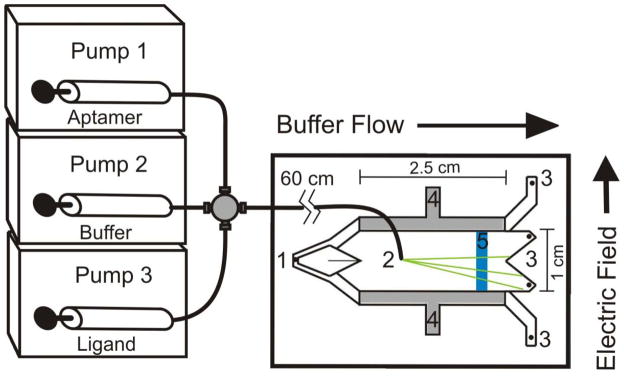
Figure 1.
Schematic showing gradient sample pumping, μFFE separation and on-chip LIF detection of analytes. A LabView computer program controlled the flow rates of pumps 2 and 3 to generate a concentration gradient of ligand. Sample was pumped into the separation channel through an access hole (2). Separation buffer was introduced into the chip via a hole (1) and carried the sample toward the exit holes (3). A separation potential was applied to the electrodes (4) to achieve analyte separation (green lines). A laser beam was expanded into a line (5) and projected across the separation channel. LIF detection was performed via microscope with CCD camera positioned perpendicular to the plane of the page.

