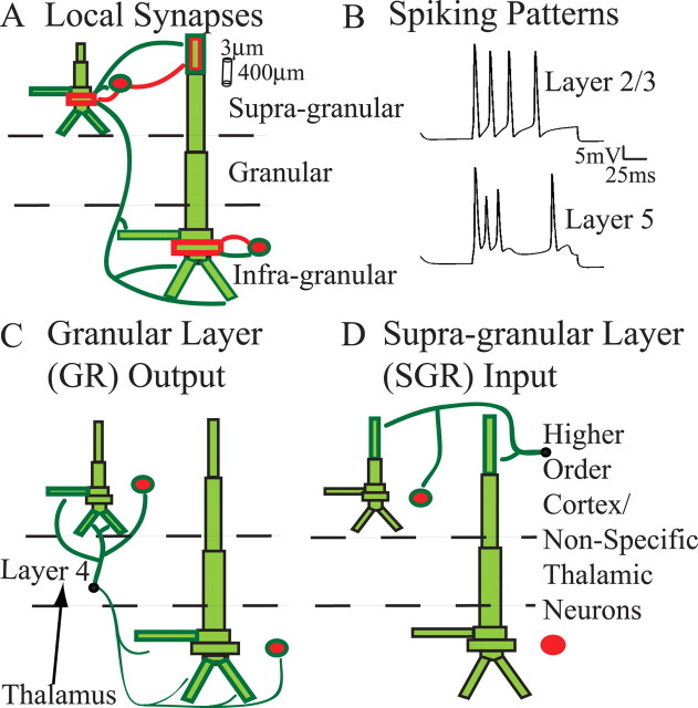
Figure 2.
Model SI network architecture. Ten PNs and 3 INs were included per layer. Excitatory (dark green) and inhibitory (red) synaptic connections were set as depicted. Bold outlined dendrites were contacted. A, Local synapses. Within-layer PN-to-PN synapses (not shown) were also present on dark green outlined dendrites. Each set of synaptic weights had a Gaussian spatial profile (Table 2). B, Spiking patterns evoked by somatic injected current (1 nA, 100 ms; no synaptic input). C, Connection pattern of output from the GR. The black arrow is only schematic, because lemniscal thalamic input was not explicitly modeled. D, Connection pattern of exogenous input to the SGR, presumably from a higher-order cortical and/or nonspecific thalamic neurons. The output from GR and input to SGR were modeled as spike train generators with a predetermined temporal profile and synaptic strength (Table 3).

