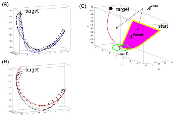
Figure 2.

Trajectory geometric measures of interest. (A) Twisting the line is defined by the angle between two consecutive vectors normal to the plane spanned by projecting the acceleration vector onto an ideal geodesic curve. Blue trajectory is jerky (segmented) from the learning data, black trajectory is modelled (see Additional file 1). Blue dots mark the critical points (speed maxima) of the segments. (B) Same twisting measure in the smooth automated case. Red dot is the single velocity peak. Black is the modelled path. (C) Ratios of interest: For each hand trajectory the curve was re-sampled at equally spaced intervals. The points along the curve were projected on the Euclidean straight line joining the start and target locations. The point of maximum bending was obtained and the area enclosed between the lined and the curve computed and denoted partial area APartial. To obtain the area ratio this quantity was divided by the total area enclosed between the curve and the line, denoted ATotal. The perimeters were similarly obtained using the length of the curves instead.
