
Fig. 5.
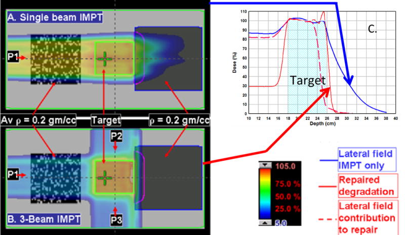
IMPT bean degradation repair by depositing doses from different directions. (A) A single lateral IMPT beam passing through a textured lung-like medium with an average ρ value of 0.2 gm/cc. After passing through the target, the beam enters a uniform medium with a ρ value of 0.2 gm/cc. The degradation of the distal edge of the beam corresponds to the dose profile along the horizontal axis (the blue line in panel C). If the beam had passed through a uniform low-density medium upstream, the degradation would not have occurred. (B) The addition of AP and PA IMPT beams and use of a negative margin for the lateral beam to deposit no more than 10% of its maximum dose distal to the target. (C) The optimization process compensated for the resulting loss of target coverage by adjusting the energies and intensities of the pencils of the AP and PA beams. The resulting dose profile along the horizontal axis is indicated by the solid red line in panel C. The dashed red line is the renormalized (to 100% at the isocenter) contribution of the lateral beam to the total dose represented by the solid red line.