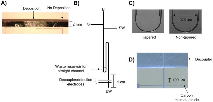
Figure 1.
A) Palladium electrodeposition on a palladium decoupler using −100 mV (vs Ag/AgCl, 3 depositions, 90 sec. each in duration); B) serpentine microchip used for the pinched injection scheme. The labels are as follows: B, buffer reservoir; BW, buffer waste; S, sample; and SW, sample waste. The dotted circle indicates the BW reservoir for a straight channel microchip; C) micrographs of the asymmetrically tapered turn and non-tapered turn; D) Micrograph showing palladium decoupler and carbon ink electrode reversibly sealed over the electrophoresis channel.

