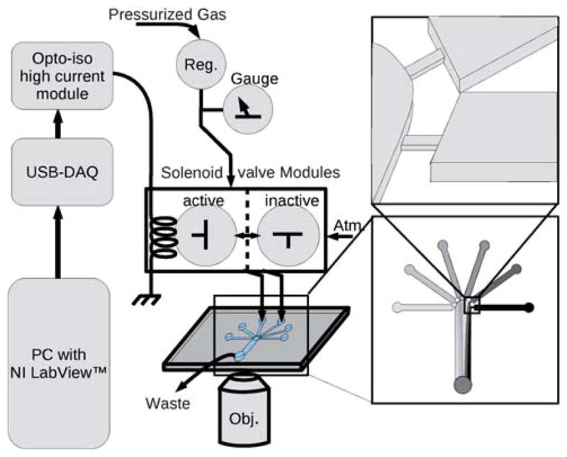
Fig. 1.

A schematic of the apparatus shows the computer (PC) at left connected to the solenoid valves through the USB-6008 DAQ device and the high power optical isolator board (Opto-iso high current module). The solenoid gas valves are 3-way normally closed type. Without current (shown as ‘inactive’) the valve is open to atmospheric pressure (Atm.). With applied current (‘active’) the valve connects the input pressure (Pressurized Gas) to the fluid in the on-chip reservoir. The input pressure is controlled with a micro regulator (Reg.). The chip is shown with expanded diagrams at right to show the narrow and shallow flow restrictions, which reduce backflow to unpressurized channels.
