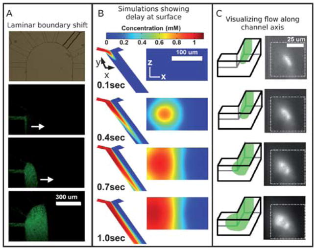
Fig. 2.
(A) From top to bottom, a micrograph shows the 8 inlets and the wide outlet, followed by fluorescence micrographs of green fluorescent beads (100 nm diameter) flowing into the wide outlet channel from the far left inlet channel. The flow exits at bottom, but the fluorescent front can be seen to move from left to right as laminar flow is established between flow from the leftmost and rightmost channels, illustrating the lateral front movement that would move dissolved stimulant across the surface. (B) Simulations of the fluid flow reveal the disparity in arrival time between fluid in the bulk and that near the surface. Although the dissolved solutes from the left (red shades) seem to have arrived at a location within the channel as seen from above, the cross section view at a position halfway down the channel reveals that it takes additional time for the solutes to actually reach the surface. (C) A schematic and micrographs show laminar flow along the left side of a microchannel as visualized by looking down the axis of the channel; in the micrographs on the right, a suspension of green fluorescent beads (20 nm diameter) can be seen to arrive in the center of the channel first and then spread toward the left side of the channel, qualitatively agreeing with the simulation shown in (B).

