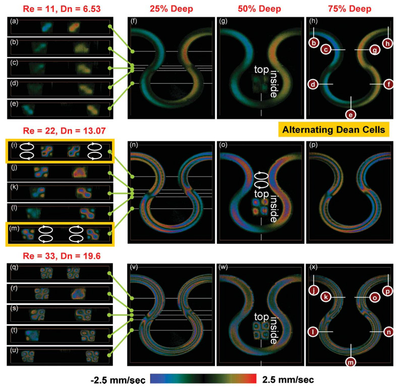
Fig. 3.
The liquid velocity vy(X, Y, Z) projected on the incident light in the area of interest. The velocity field shows a pair of counter-rotating vortices indicated above the inset in (o). Since the curvature is alternating, the rotational direction of the vortices is also alternating as shown by comparing (i) to (m). (a–e, i–m, q–u) The y-component velocity field vy(X, Y, Z) sectioned by the XY-planes. (f–h, n–p, v–x) The y-component velocity field vy(X, Y, Z) sectioned by the XZ-planes. (Insets in g, o, w) The y-component velocity field vy(X, Y, Z) sectioned by the YZ-planes.

