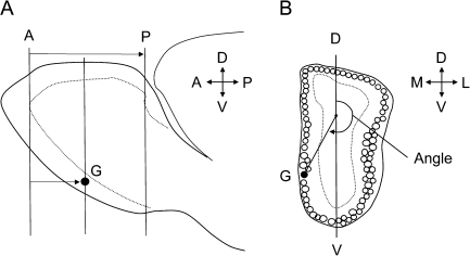
Figure 1.
Diagram illustrating the method used to measure the position of P2 glomeruli. (A) Lateral view of the olfactory bulb showing lines representing coronal sections passing through the plane of the anterior reference section (A), posterior reference section (P), and section containing the glomerulus (G). The AP distance defines the olfactory bulb length and AG distance the position of the glomerulus. (B) Diagram of a coronal section of the olfactory bulb passing through a glomerulus G. A point one-third the distance along a line (D–V) passing though the dorsal and ventral glomerular layers, and a vector extending to the center of the glomerulus G, was used to measure the angle that defines the position of the glomerulus within a section. Both AG distance and angle were used to determine the coordinate position of each glomerulus (see Materials and methods for details). M, medial; L, lateral; D, dorsal; V, ventral.

