Figure 1.

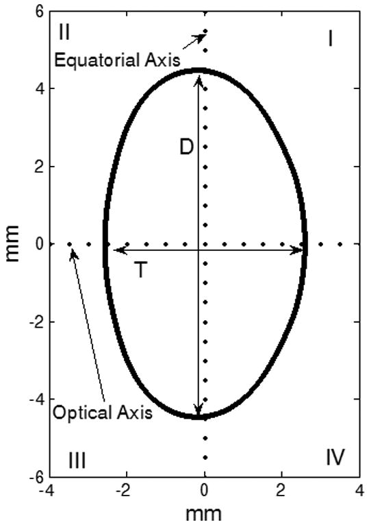
The co-ordinate system for the Fourier model. The lens anterior surface was placed in quadrants II and III and the posterior surface was placed in the quadrants I and IV. T and D represent the thickness and diameter of the lens.

The co-ordinate system for the Fourier model. The lens anterior surface was placed in quadrants II and III and the posterior surface was placed in the quadrants I and IV. T and D represent the thickness and diameter of the lens.