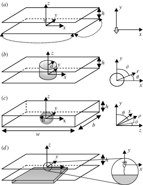
Figure 1.
(a) Stokeslet between parallel walls. The stokeslet is represented by a grey arrow pointing in the −ey direction and the dotted lines represent periodic boundaries. The upper and lower boundaries (parallel to the x−y plane) are no-slip. (b) Brinkman approximation geometry. (c) Simulation geometry. The upper and lower boundaries are no-slip. The right-hand and left-hand boundaries are open, and the front and back boundaries are slip. (d) A schematic view of the experimental set-up. Vorticella are grown on the narrow edge of a glass coverslip (grey box), which is inserted midway between two slides, a distance h apart.

