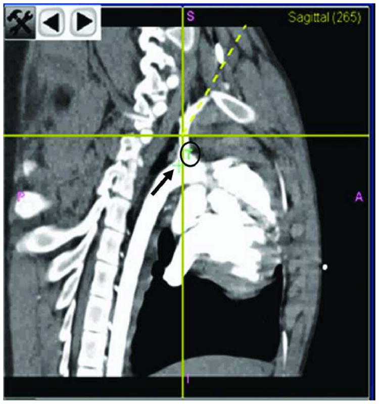
Figure 4.

Panel B is enlarged. It displays the position of the tracked tool in the sagittal plane. The small green cross (black arrow) is the actual position of the target. The “T” (black circle) explains the significance of the small green cross. The yellow crossing lines indicate the position of the tracked tool. The yellow dotted line is the direction of the tracked tool.
