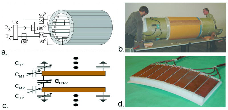
Figure 1.
7 T TEM body and surface coils (14). Figure 1a. shows a schematic diagram of the TEM body coil connected for four-port transmit and receive (1). Figure 1b shows the body coil mounted on the Siemens bore tube for insertion into the Siemens Sonata gradients. The transmission line “rungs” of the coil occupy the middle third (33 cm) of the one-meter coil as shown. The cavity or shield component of the coil is slotted for gradient induced eddy current attenuation and TEM element segregation. Figure 1c shows a schematic of a section of the TEM surface coil. The capacitances CT, CM, and CD are for tuning, matching, and decoupling the independent elements respectively. Figure 1d shows an eight element TEM surface coil (32 cm × 15 cm) built of eight sets of two parallel copper strips separted by a 2 cm thick polytetrafluoroethylene dielectric, with eight independent drive cables connected.

