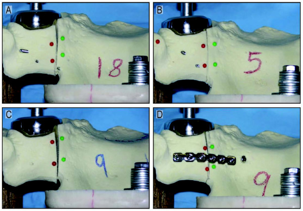
Figure 3.

Representative photos of displacement at the fracture site with all four fixation schemes at 2000 N of loading are shown. (A) Anterior column plate; (B) Anterior column plate with posterior column lag screw; (C) Anterior column locking plate; (D) Posterior column plate with anterior column lag screw.
