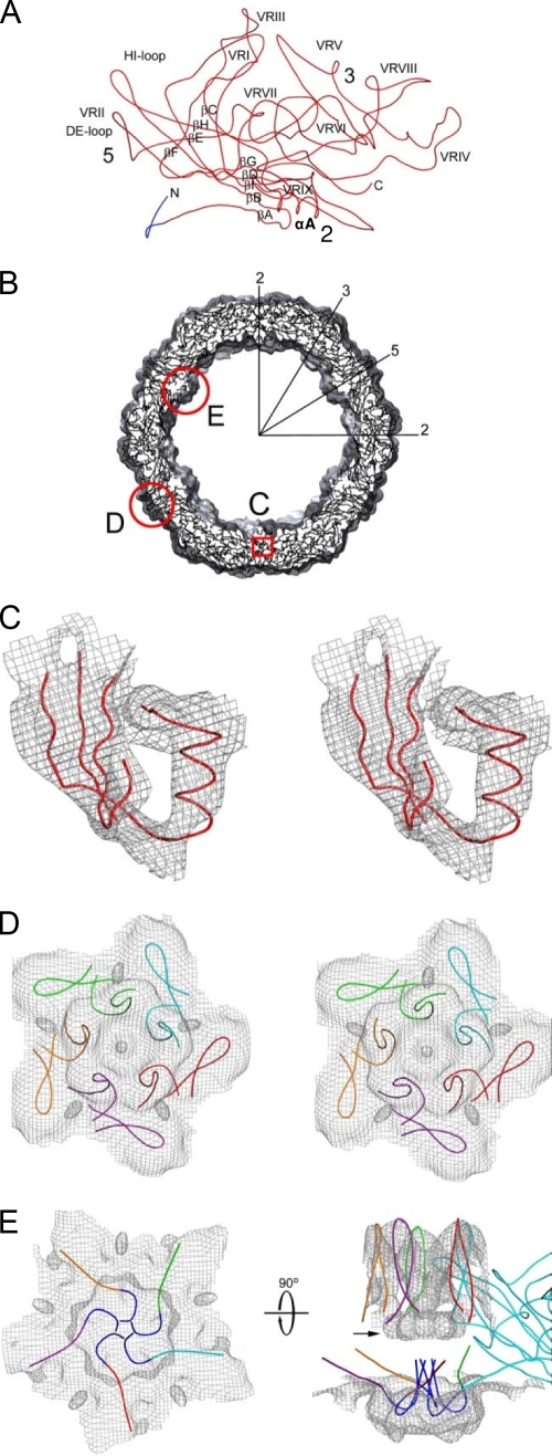
FIG. 5.
Pseudo-atomic model of HBoV VP2. (A) A Cα trace of the VP2 pseudo-atomic model. Labels highlight the β-strand regions (BIDG-CHEF) that form the core β-barrel, the α-helix A (αA), the DE and HI loops, and the nine predicted variable surface regions (VR-I to VR-IX). The approximate 2-, 3-, and 5-fold axes are shown by the numbers 2, 3, and 5, respectively. The dark-blue, N-terminal portion of the model represents nine residues that were not included in the initial HBoV homology model but that can be fit into the HBoV cryo-reconstruction. (B) An equatorial slab of pseudo-atomic HBoV VP2 monomers docked into the reconstructed density map. Several icosahedral symmetry axes are labeled as described in the legend of Fig. 2B. Regions outlined in red are enlarged in subsequent panels to further emphasize the fit of the model. (C) Stereo view of a small portion of the VP2 model (in red) showing the structurally conserved, β-barrel core (β-strands A, B, I, D, and G) and αA helix modeled into the reconstructed density (gray mesh, contoured at a threshold of 3.3 σ). (D) Same as panel C for a view of the capsid region surrounding the 5-fold axis, showing the fit of five, symmetry-related, DE loop β-ribbon models that form the cylindrical channel and the fit of five HI loops that form the petal-like structures on the canyon floor. The five VP2 monomers are distinguished by color. (E) The left model shows the same region as panel D but viewed from inside the capsid and highlighting the channel plug. Residues 28 to 36 in the HBoV VP2 model are shown in blue. The model at right is the same but viewed from the side to show the model of one monomer and the DE loops of four symmetry-related monomers at the pore of the 5-fold channel. N-terminal residues 28 to 36 (in blue) were modeled as extending up into the 5-fold channel. The color scheme is the same as in panel D.

