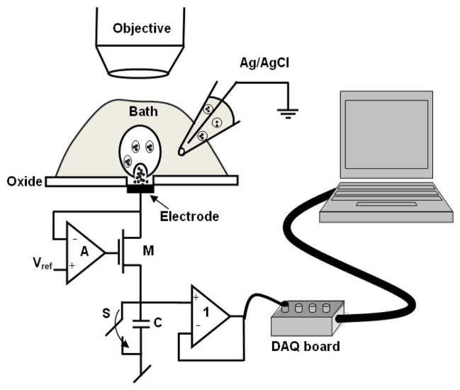
Fig. 4.
Schematic of the experimental setup: The printed circuit board is mounted on an adjustable microscope stage. A pipette holder is placed on another adjustable microscope stage to position the pipette near the electrode. The microscope along with the adjustable holders is housed in a properly grounded faraday cage to eliminate power line noise. The output is connected to a 16-bit A/D converter, clocked externally to sample data at the end of the integration period. The A/D converter is connected to a computer where the data is acquired and analyzed.

