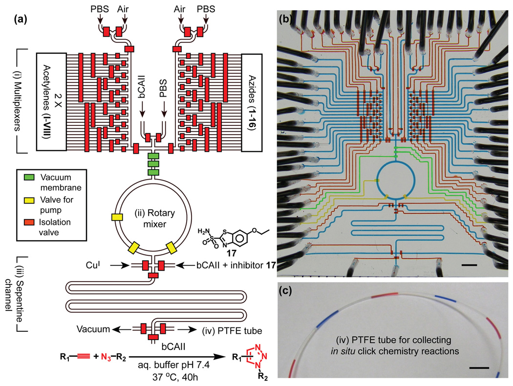
Fig 1.
(a) Schematic representation of the 2nd-generation integrated microfluidic platform. The operation of the circuit was computer controlled using color-coded pressure-driven valves: red – positive pressure, off/on; yellow – peristaltic pumping; green – vacuum. (b) Optical image of the actual device. The various channels were loaded with dyes to visualize the different components: red, yellow and green as in part (a) and blue indicated the fluidic channels. (c) The PTFE tubing for off-chip incubation and storage of the reaction mixture slugs. Again, blue and red dyes are used for visualization. Black scale bars are 3 mm.

