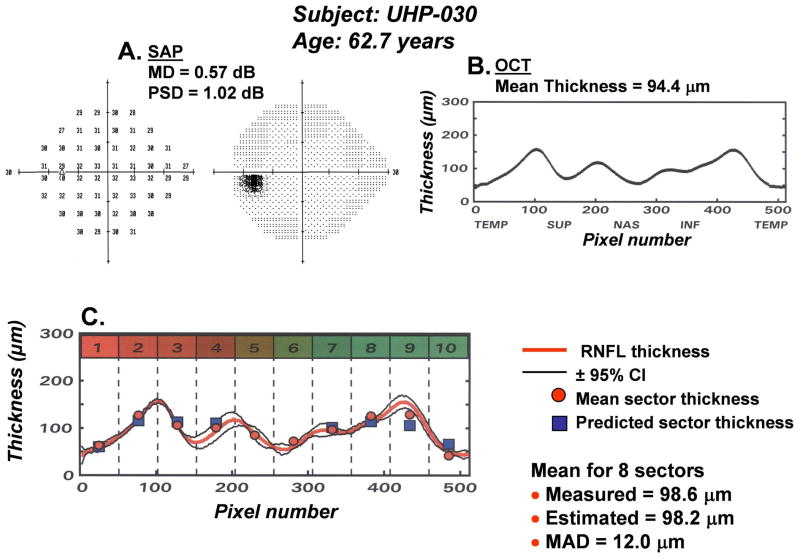
Figure 14.
An example of a method for mapping perimetric neural losses onto the TSNIT curve of RNFL thickness. The plan for mapping SAP areas onto sectors of the OCT scan described in Fig. 6, was used to derive an estimate of RNFL thickness from SAP measurements (A) and compared to the measured thickness from OCT measurements (B). The results for a glaucoma suspect with normal SAP and OCT are presented (C), with the RNFL scan shown by the thick solid line and the 95% CIs, based on three repeated measures, as the thin lines. The mean RNFL thicknesses from the OCT measurements are indicated by the solid circle at the mid-point of each sector and the RNFL thicknesses that were predicted from the corresponding SAP measurements are presented as the solid square symbols.

