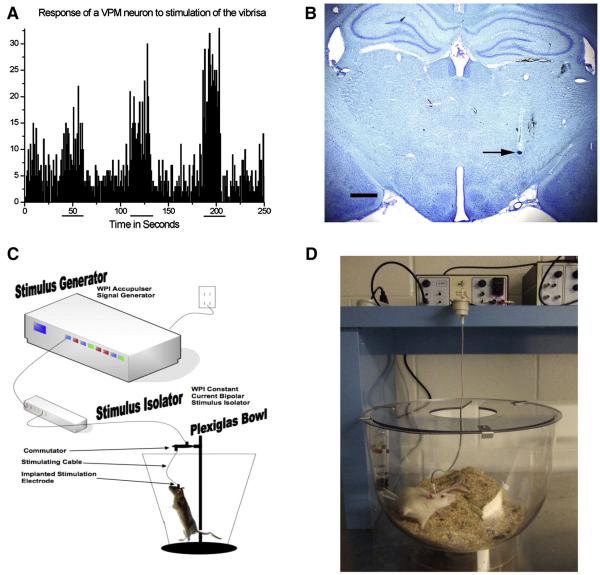
Figure 2. Extracellular Recording-Guided Electrode Placement in STN and Long Term STN DBS Platform.
A. Response of a neuron within the ventral posterior medial nucleus of the thalamus (VPM) to stimulation of the contralateral vibrissa, stimulation period indicated by horizontal lines beneath x axis. This VPM landmark is used to determine appropriate AP and ML electrode placement, the STN is located 0.5 – 1.0 mm ventral to this site and is readily distinguishable by a sudden increase of irregular spikes firing at a high rate. B. Dye infusion within STN recording site (arrow). After the coordinates of the STN were identified a bipolar concentric microelectrode was implanted with the electrode fixed in place using dental acrylic and bone screws. Scale Bar = 1000 μM. C. Schematic of an individual stimulation setup, including an Accupulser Signal Generator (World Precision Instruments, WPI) connected to a Constant Current Bipolar Stimulus Isolator (WPI) that is connected to the concentric bipolar stimulating electrode implanted into the rat STN and secured using dental cement and bone screws. The rat is housed in a Raturn System Bowl (BioAnalytical Systems, Inc., BASi). The stimulator cable is routed through a commutator to allow the rat to move freely during the two week stimulation interval. D. Photograph of an individual rat undergoing STN-DBS during the two week stimulation interval.

