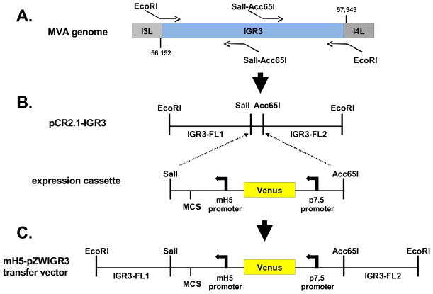
Figure 1. Construction of recombinant MVA-pp65-IGR3.
(A) Schematic for mH5-pZWIGR3 transfer vector construction. Shown is a representation of the region of the MVA genome where IGR3 is located between the I3L (ORF 064) and I4L (ORF 065) genes. Two sets of primers were used to amplify individual regions of the IGR3 that would be used in the final transfer vector shown in C. The left most portion is approximately 596 base pairs and corresponds to IGR3-FL1, while the right fragment is approximately 607 base pairs and represents IGR3-FL2. Sequences of the primers and methods for amplification are described in Table 1 and Materials and Methods. The IGR3 region of the MVA genome was first amplified using primers containing EcoRI sites for cloning into pCR2.1 (pCR2.1-IGR3). (B) An expression cassette containing a multiple cloning site (MCS), modified H5 promoter (mH5) and fluorescent selection marker cassette (Venus™, Clontech) was inserted into pCR2.1-IGR3 using SalI and Acc65I restriction sites. The Sal1-Acc65I fragment bisects the IGR3 amplified region into two segments that are referred to as IGR3-FL1 and IGR3-FL2. (C) The expression cassette flanked by IGR3 (FL1 and FL2) was then inserted into the mH5-pZWIIA transfer vector (Wang et al, In Press) using EcoRI restriction sites (mH5-pZWIGR3). The mH5-pZWIGR3 transfer vector was used to generate recombinant MVA (rMVA-pp65-IGR3) by homologous recombination. Procedures and primer sequences are described in Table 1 and Materials and Methods.

