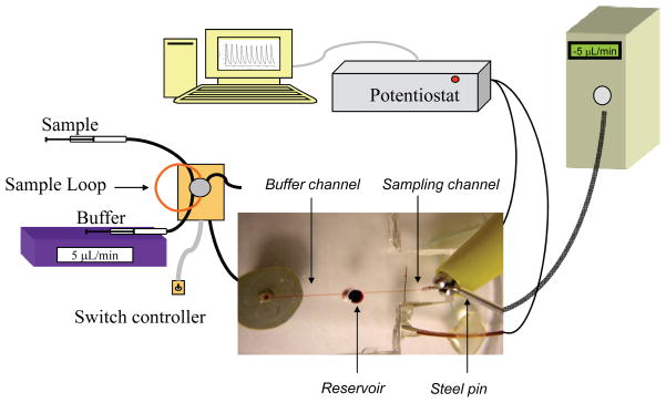
Figure 2.
Amperometric setup for the microfluidic device. A syringe pump delivers buffer to a 6-port injection valve containing a 5 μL sample loop made of capillary tubing. As buffer passes through the sample loop it carries sample away from the injector to the fluidic device. The capillary tubing running from the injector is connected to a glass substrate by a Nanoport fitting. Buffer carrying analyte passes through the glass substrate, through the bottom layer of PDMS, and into the fluidic channel. As buffer reaches the 1/8″ reservoir it is drawn away by the negative pressure of the syringe pump connected to the steel pin at the terminal end of the fluidic channel. The working electrode residing in the path of the fluidic channel is connected to the potentiostat using a copper wire while the steel pin quasi-reference electrode is connected directly to the coupled potentiostat lead. The digital image displays the device in relation to amperometric setup (not to scale).

