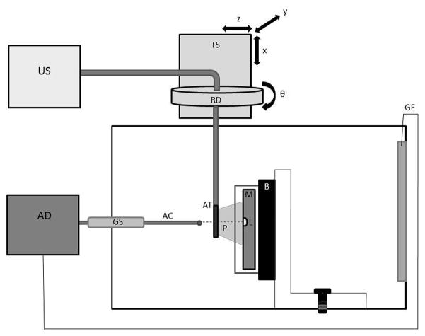
Fig. 1.
The in vitro experimental chamber. A myocardial (M) sample rests in front of a sound absorbing backing (B) on a vertical mount box. A lesion (L) was made using a radiofrequency ablation device (AD) connected to a foil ground electrode (GE) and an ablation catheter (AC) brought into contact with the myocardium though a guide sheath (GS). An ultrasound scanner (US) imaged the lesion with an AcuNav™ transducer (AT). The imaging catheter was adjusted to the desired imaging plane (IP) using a translation stage (TS) and rotation dial (RD).

