
Fig. 1. Layout of a simple feedback controlled optical trap.
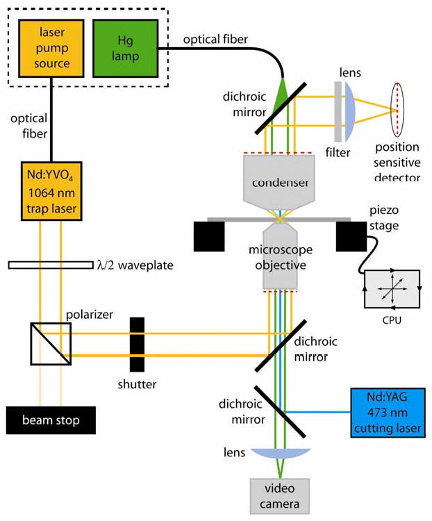
The diode pump source for the 1064 nm laser and the mercury arc lamp are located outside the microscope room (dashed box) to minimize heat and noise and are coupled via optical fibers to the laser head and microscope. The waveplate and polarizer select a fraction of the total power from the trapping laser as a stiffness adjustment. An operator-controlled shutter is used to turn the trap on and off during experiments. The trapping beam enters and exits the microscope via dichroic mirrors which pass light in the visible range for specimen illumination and laser scission. A filter and lens isolates the trapping beam and images it on a position sensitive detector. Beam position data from the detector is used to move the piezo specimen stage by computer controlled feedback. A video camera is used for contrast-enhanced DIC imaging of individual microtubules. A second dichroic introduces the 473 nm microtubule cutting laser into the microscope objective.