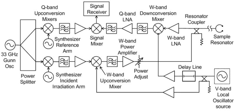
Figure 3.

Frequency-swept W-band EPR bridge functional schematic. See Fig. 2 for components key. Nominally, the incident irradiation arm synthesizer is set to 2 GHz, and the reference arm synthesizer is set to 3 GHz. 33 GHz is upconverted to 35 GHz and then to 59 GHz. The EPR signal at 94 GHz is downconverted to 35 GHz and then to 1 GHz at the signal mixer output.
