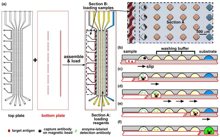
Figure 1.
Performing heterogeneous immunoassays with multiple nL samples in SlipChip. (a) A schematic of the SlipChip designed for calibration on the two plates of microfabricated glass. The top plate of this SlipChip (outlined in black) contained inlets, outlets, and wells for the various reagents (Section A), and inlets, outlets, and ducts to load the samples: six standard solutions (Section B). All wells and ducts are 80 μm deep. The bottom plate (outlined in red) of this SlipChip contained the 80 μm deep ducts to load the reagents (Section A), and 10 μm deep wells for the sample (Section B). The two plates are assembled to form the fluidic path for loading the reagents and samples. In Section A, the wells were loaded with reagents. The grey wells of row 1 were loaded with the solution containing magnetic beads coupled with the capture antibody and an enzyme-labeled detection antibody. Wells in rows 2–5 (yellow) contained the washing buffer. Wells in row 6 (blue) contained the substrate. Section B is designed to load six samples into seven wells each. A microphotograph on the right shows the wells filled with different dye solutions (rows 2–6 of section A and Section B) or a suspension of beads (row 1 of section A). (b–f) Schematics of step-by–step operation of the bead-based immunoassay in SlipChip. See details in text.

