
Figure 2.
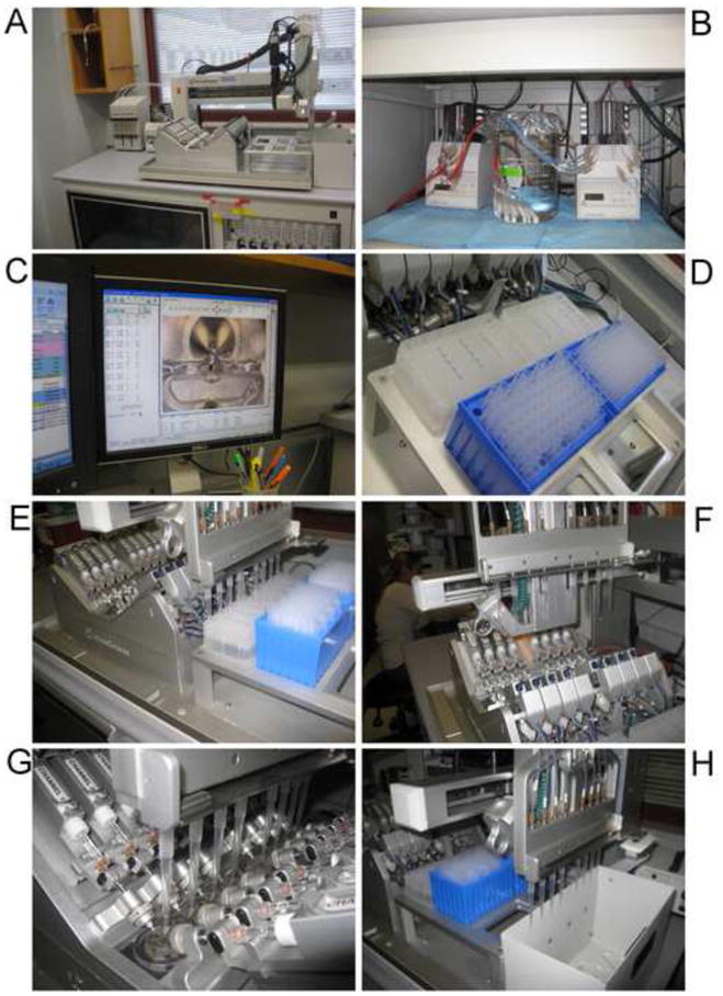
OpusXpress in action. A) The flight deck: the “V8” array of chambers is in the center. Behind the chambers to the left is the peristaltic pump for bath outflow and the syringe pumps for the pipette delivery system. To the right of the V8 are the racks for drug well plates and pipette tips, and furthest right is the bin for used tips. The video camera arm is in the rear, in its “homed” position. B) The two peristaltic pumps for the bath buffers. Tubes for the eight “buffer A” lines are in a single reservoir beaker. Each line has a replaceable filter at the end. C) One of the computer monitors with a chamber in view on the camera window. D) Drug wells and pipette tips in place. E) Aspiration of drug solutions. F) Movement of the tips toward the chambers. G) Drug delivery. H) Disposal of used tips.