
Figure 1.
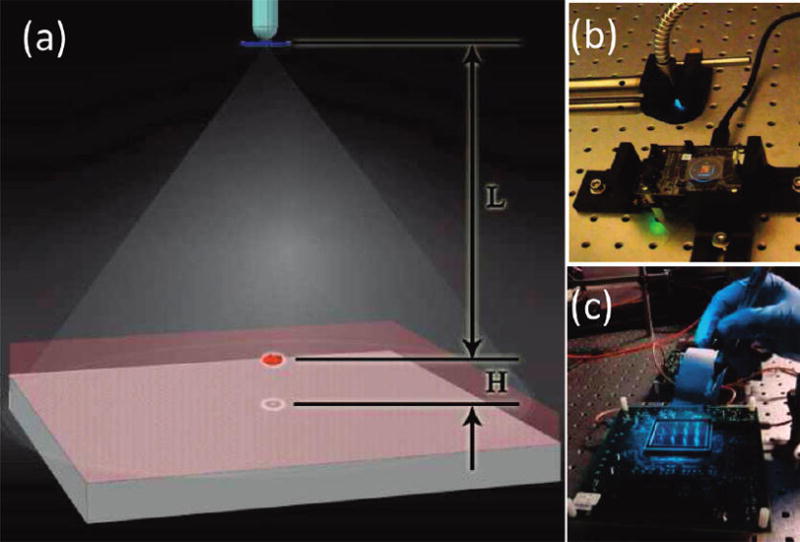
(a) Schematic diagram of the lensless holographic imaging platform is shown. (b) The corresponding experimental setup, which uses a xenon lamp coupled to a monochromator for tuning of the illumination wavelength, is illustrated. The source is filtered by an aperture size of D ≈ 50–100 μm before illuminating the cells. The FOV of the CMOS sensor in panel (b) is ~24 mm2, as further illustrated in Figure 1 in the Supporting Information. (c) A holographic imaging platform that has a significantly larger FOV (~18 cm2) is shown (see Figure 9 for further information). L and H denote the aperture-to-cell-plane distance and the cell-plane-to-detector-plane distance, respectively. Typically, L = 2–20 cm, and H < ~ 1–2 mm.