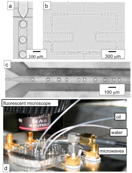
Fig. 2.

(a) A micrograph of the flow-focusing drop maker, (b) The two sets of drop splitters in series, (c) a micrograph of the microwave heater, the dark regions that run parallel to the fluid channel are the metal lines, (d) a photograph of the microfluidic device, connected to the microwave amplifier with an SMA cable, on top of a hot place, underneath the fluorescent microscope.
