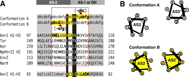
Figure 8. Output Mechanism Involving “Stutter Compensation”.
(A) Model for signal transfer that shifts the position of a stutter on either side of the AS2 junction with AS1 (poly-HAMPs) or output helices (OH) (canonical HAMPs). Helical junctions are shown for representative HAMP domains and Aer2 HAMP 2-3. Stutters (bold) are defined as either an insertion of four residues or a deletion of three residues in the heptad repeat (a-g) and effect adjacent residues (yellow highlight). Residues at the junction switch heptad positions (black highlight) and are compatible with different heptad positions. This model predicts that Aer2 HAMP2 contains a stutter (shown in bold) in AS1 (bottom sequence). Whereas the heptad assignments in HAMP2 AS-1 are as shown, the splayed helices of AS-1 do not generate a true hendecad repeat but do contain an elongated i to i+4 (E66-A70) hydrogen bond distance (3.5 Å) typical of stutters. (B) Helical wheel diagrams of AS2 helices in conformation A (HAMP1/3) and B (HAMP2) highlighting the helical rotation and translation associated with a stutter (dotted line) in AS2.

