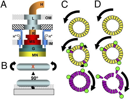
Fig. 1.
(A) Schematic view of the E. coli flagellar motor. Rotor elements are as follows: MN (FliMN), G (FliG), MS (MS ring), R (rod), and H (hook). Stationary elements are P (P ring), L (L ring), and M (MotA4MotB2) complex. Mot complexes attach to the cell wall (hatched), conduct H+ through the membrane, and interact with FliG. IM and OM denote the inner and outer membranes. (B) Cartoon of a tethered cell. A sheared flagellar filament is affixed by using antifilament antibody. The cell body counter rotates to the direction of motor rotation. The red X marks the point at which the tethering flagellum is located. The wavy pattern indicates the evanescent wave generated by TIRF. (C) The domino model for cooperative switching within the motor. The motor at the top is spinning CCW. CheY-P binding to FliM (trapezoids) initiates a wave of conformational change, shown as CW-facing arrows, to place the C ring in the CW conformation. (D) FliM destabilization model for cooperative switching. CheY-P (green circle) binding to FliM destabilizes the FliM ring, which allows the motor to “relax” into the CW conformation. Both models are speculative, and the scenario shown in D exists only in the imagination of the author.

