
Fig. 1.
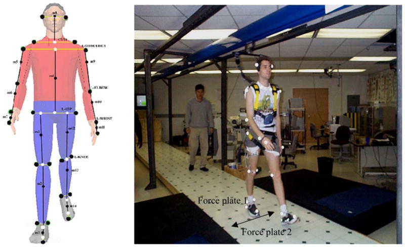
Field layout of the experiment including fall arresting harness and locations of force plates. Lateral moveable floor surfaces at the force plate locations (arrow). On the left side, 26 reflective marker positions (two heel markers hidden on the illustration) are also illustrated.