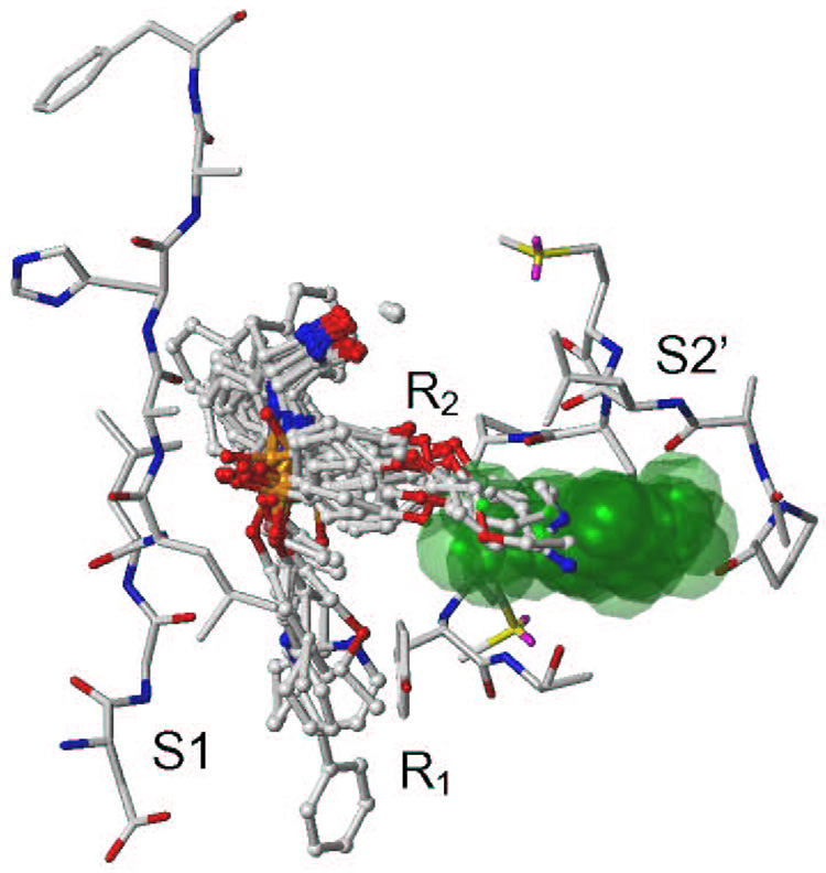
Figure 6.
The binding modes of compounds with longer R1 (compounds 4 – 9) and R2 (18 – 22) substituents (Table 1) shown in ball and stick mode. Compounds with smaller R1 and R2 substituents follow a similar pattern. The catalytic zinc is represented as sphere. The empty pocket of the S2’ subsite, created with the SiteID module of Sybyl,96 is represented by transparent green space fill. The residues of the S2’ and S1 subsites as well as residues surrounding the empty pocket for compound 4 are shown in atom color in the capped stick mode. All structures are time-averaged structures from MD simulation (Step 3).

