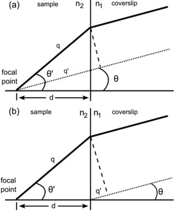
Fig. 1.
Ray diagram of the depth aberration. (a) Diagrams the path length difference (n2q-n1q’) between an unrefracted ray (dashed line) from a point a depth d below the cover slip and a ray that is refracted at the interface (solid line). Compensating for this path length difference in the back pupil plane will correct the spherical aberration. (b) Shows the path length difference (n2q-n1q’) between a ray from a point just below the cover slip (dashed line) and a ray a depth d below the interface. Compensating for this path length difference in the back pupil plane will focus to a depth d and correct for spherical aberration.

