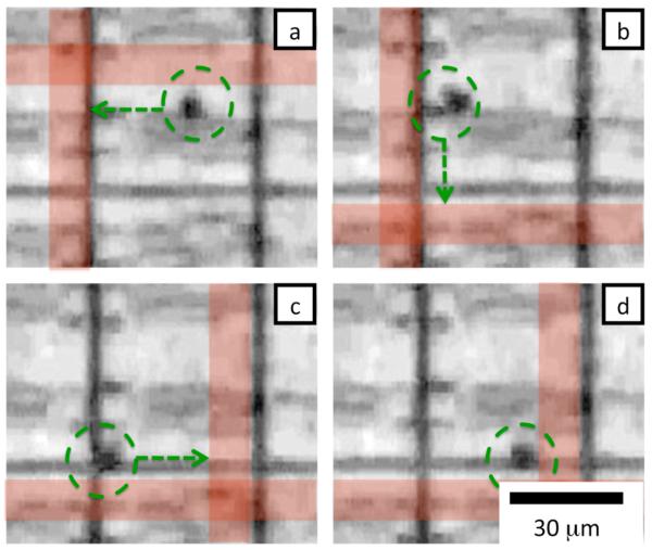
Fig. 4.
Time sequence of magnetic trapping and positioning of a magnetic bead. Magnetic wires in the matrix are turned on in sequence to position the bead. The position of the particle is marked with a green circle. The direction that the bead is being pulled is marked with a green arrow. The red lines indicate which magnetic wires in the matrix have been turned on, the actual wires are buried under the DEP pixels and are not visible. Each frame (a-d) is separated by roughly 2 sec.

