
Fig. 1.
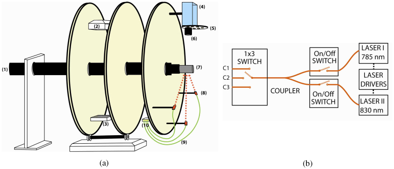
(a) The schematic of the multi-modality gantry-based system. The XCT gantry was expanded and optical imaging components were installed. A sample holder was designed to translate the sample between XCT and optical imaging systems. The components that are seen in the diagram: (1) the sample holder, (2) x-ray source, (3) x-ray detector, (4) CCD camera, (5) filter wheel, (6) lens, (7) phantom, (8) fiber optic collimator, (9) optical fibers, (10) fiber optic switch. (b) The light delivery components. On-off switches were used to select the desired illumination wavelength. A 50/50 fiber optic coupler was used to combine both laser output. A 1 x 3 fiber optic switch allowed the sequential activation of any one the three source sites.