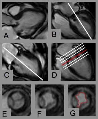
Figure 1.

Slice positioning for prosthetic orifice planimetry. A) and B) 3- and 4-chamber-view showing the mitral bioprosthesis. Planning the next slice in the 4-chamber view along the transprosthetic jet (white line). C) Again planning the next plane centrally through the transprosthetic jet. D) Positioning a stack of slices perpendicular to the jet covering the prosthesis during cardiac motion. E) and F) Cross section of the mitral bioprosthesis in systole and diastole. G) Manual contouring of the largest diastolic orifice area.
