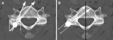
Fig. 1.
The method of screw insertion in each period. a The method of Period E. According to the original method provided by Abumi et al. an insertion hole is made on the posterior surface of the lateral mass by a high-speed burr under the guidance of lateral fluoroscopy at the bisecting point of the width of each facet joint. Then, a screw hole is excavated by a pedicle probe at the axial angle from 25° to 45°. Thin white lines represent the width of a facet joint. A white circle is the bisecting point of the width of a facet joint. White arrows are acceptable screw trajectories. b The method of Period M: an insertion point is made on the surface of the lateral mass where the pedicle axis passes through. A screw hole is excavated at the angle of 45° or more. Thin white arrows show the pedicle axis, which is defined as a perpendicular line to a line on the shortest distance between the transverse foramen and the lateral recess. A white circle is an inserting point just on the surface where the pedicle axis passes through. Thick white arrows are aiming screw trajectories. A black line represents perpendicular line to the posterior surface of the vertebral body, which is a base line of measurement of both anatomical pedicle angles (APA) and screw trajectory angles (STA)

