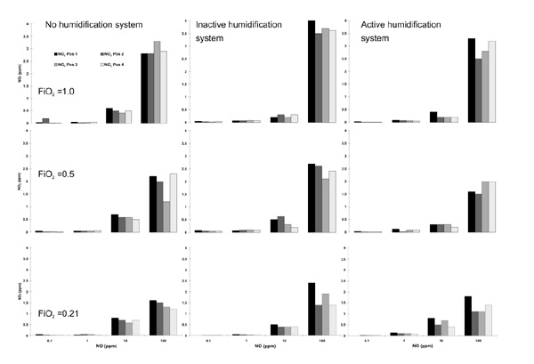
Figure 5.

Individual nitrix dioxide (NO2) measurements in parts per million (ppm, y-axis) for the different nitric oxide (NO) concentrations adjusted (x-axis, NO) and the different FiO2 values as well as the different circuit setups. Each line of figures represents the different settings for FiO2. Each column of figures represents the different setups for the heating system.
