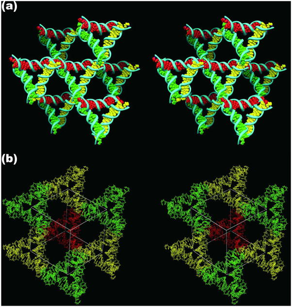
Figure 2. The Lattice Formed by the Tensegrity Triangles.
(a) The Surroundings of an Individual Triangle. This stereoscopic simplified image distinguishes the three independent directions by the colors (red, green and yellow) of their base pairs. Thus, the central triangle is shown flanked by three other pairs of triangles in the three differently colored directions. (b) The Rhombohedral Cavity Formed by the Tensegrity Triangles. This stereoscopic projection shows seven of the eight tensegrity triangles that comprise the corners of the rhombohedron. The outline of the cavity is shown in white. The red triangle at the back connects through one edge each to the three yellow triangles that lie in a plane somewhat closer to the viewer. The yellow triangles are connected through two edges each to two different green triangles that are in a plane even nearer the viewer. A final triangle that would cap the structure has been omitted for clarity. This triangle would be directly above the red triangle, and would be even closer to the viewer than the green triangles.

