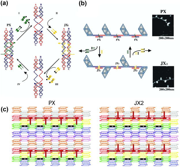
Figure 5. DNA-Based Nanomechanical Devices.
(a) The Machine Cycle of a PX-JX2 Device. Starting with the PX state on the left, the green set strands are removed by their complements (Process I) to leave an unstructured frame. The addition of the yellow set strands (process II) converts the frame to the JX2 state, in which the top and bottom domains are rotated a half turn relative to their arrangement in the PX conformation. Processes III and IV reverse this process to return to the PX structure. (b) AFM Demonstration of the Operation of the Device. A series of DNA trapezoids are connected by devices. In the PX state, the trapezoids are in a parallel arrangement, but when the system is converted to the JX2 state, they are in a zigzag arrangement. (c) Insertion of a Device Cassette into a 2D Array. The eight TX tiles that form the array are shown in differently colored outlined tiles. For clarity the cohesive ends are shown to be the same geometrical shape, although they all contain different sequences. The domain connecting the cassette to the lattice is not shown. The cassette and reporter helix are shown as red filled components; the black marker tile is labeled ‘M’ and is shown with a black filled rectangle representing the domain of the tile that protrudes from the rest of the array. Both the cassette and the marker tile are rotated about 103° from the other components of the array (three nucleotides rotation). The PX arrangement is shown at the left and the JX2 arrangement is on the right. Note that the reporter hairpin points towards the marker tile in the PX state, but points away from it in the JX2 state.

