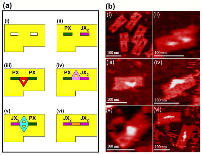
Figure 6. Schematics (a) and Atomic Force Micrographs (b) of the Origami Arrays and Capture Molecules.
Panel i of (a) illustrates the origami array containing slots for the cassettes and a notch to enable recognition of orientation; the slots and notches are visible in the AFM in (b). Panels ii show the cassettes in place; the color coding in (a) used throughout the schematics is green for the PX state and violet for the JX2 state; the presence of the cassettes is evident in the AFM image in (b). Panels iii illustrate the PX-PX state which captures a triangle pointing towards the notch in the schematic (a) and in the AFM image (b). Panels iv illustrate the PX-JX2 state (a), containing a triangle that points away from the notch, which is evident in the AFM image (b). Panels v illustrate the JX2- PX state which captures a diamond-shaped molecule (a); its shape is visible in the AFM image (b). Panels vi show the linear molecule captured by the JX2-JX2 state, both schematically (a) and in the AFM image (b).

