Figure 1.
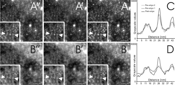
Electron energy loss micrographs. Figures A (A-A") and B (B-B") represent the electron energy loss signal of S and Cd respectively. Images A' and B' (pre-edge 1), as well as A" and B" (pre-edge 2), show the background signal of each element, whereas image A and B show the post-edge signal with the highest specific signal peak. In both image series, it is evident that there is a strong primary signal for S and Cd which enables a background subtraction to be performed. To emphasize this fact, figures C (S) and D (Cd) show the grey scale values of the sections between the two arrows, resulting in the strongest signal at the post-edge image: The peak between 20 nm and 30 nm, (black line) indicates that this object is a QD, whereas the peak between 5 nm and 15 nm shows no difference in intensity over the three images, resulting in the conclusion that this object is not a QD. The scale bar equates to 50 nm.

