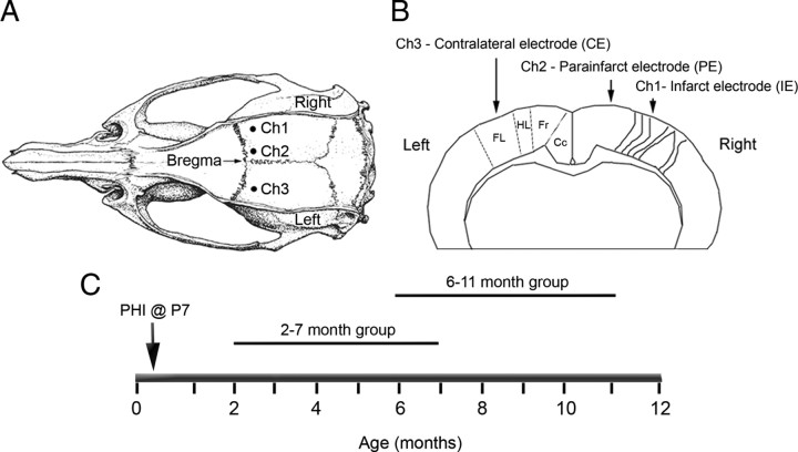
Figure 2.
Schematic diagrams of the electrode placement for chronic radio-telemetric monitoring of cortical EEG and of the recording periods in the study. A, Dorsal skull surface of rat showing locations of the three subdural, bipolar recording electrodes over the two hemispheres (modified from Paxinos and Watson, 1998). B, Schematic diagram of the coronal view for the cortical surface locations of the three subdural electrodes. The electrodes were placed over the bilateral forelimb motor and paracingulate cortices, and their respective channel numbers are denoted for the recorded cortical EEG data. Ch1, Core of the ipsilateral cortical infarct (parasagittal unparallel lines in right neocortex denote ischemic lesion, IE); Ch2, ipsilateral paracingulate neocortex (medial to cortical infarct, PE); Ch3, contralateral cortex (CE). Cc, Cingulate cortex; Fr, frontal cortex; HL, hindlimb area of cortex; FL, forelimb area of cortex. C, Schematic diagram of the two recording periods after the postnatal day 7 ligation surgery.

