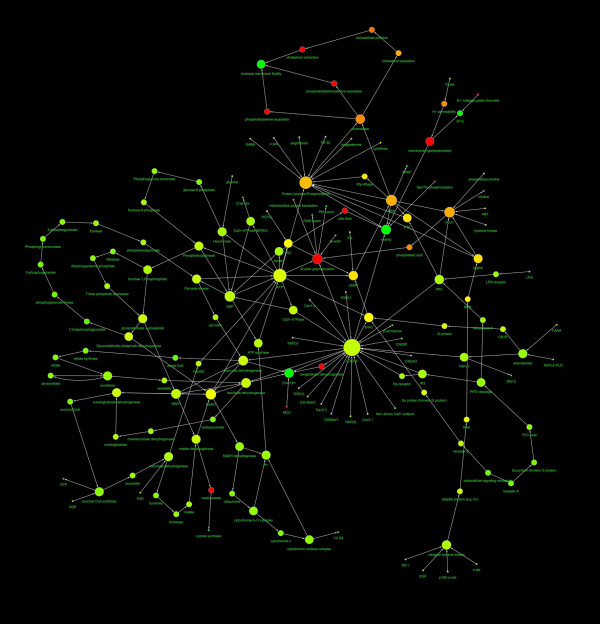
Figure 1.
Diagram showing the structure of the capacitation network. The nodes diameter is proportional to the number of links, the color varies depending on the network centrality. The direction of arrows represents the direction of the interaction (from the source to the target). The spatial network arrangement was obtained by using the Cytoscape Spring-embedded Layout (see the text for explanation).

